Product Description
|
|
Product Description
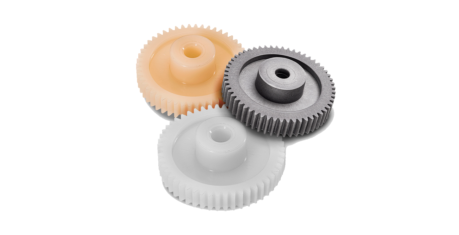
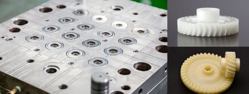
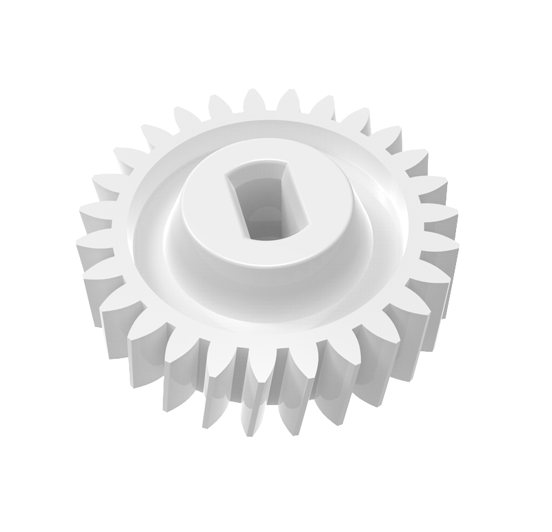
| Product name: | Custom Precision CNC Machining Small Nylon Plastic Bevel Gear |
| Marketing Type: |
Hot Product 2571 |
| Core Components: | Plastic Bevel Gear |
| Brand Name: | OEM |
| Material: | Nylon or OEM |
| Certificate: | ISO ROHS |
| Tolerance: | 0.02-0.2mm |
| Delivery Time: | 20-25 Days |
| port: | HangZhou |
Company Profile
HangZhou Dakunlun Hardware & Plastic Products Co.,Ltd. is a company engaged in Custom Products covering Custom CNC,Plastic Injection,Powder Metallurgy Parts ect. Hot Selling products include Gears,CNC Milling Parts Model Train Wheelsets Shaft,Bushing,Spacer and Brass Turning Parts ect.
Dakunlun was established in May 2006, cooperated with many enterprises at home and abroad (such as Fenda ,LG, Philips Dji and Nissan) to establish a long term friendly business relationship.Our inception is to absorb a variety of talents, improve product quality and staff quality Strict quality guarantee system and perfect management system, high-quality products after-
sales service is our foothold. Our company of “quality first, reputation first” principle, provide customers with quality and quantity of various types of products. Always uphold the “quality, integrity and pragmatic, motivated, service-oriented” business philosophy, and apply to the company’s management and operating. In face of fierce competition, our company’s system is constantly being improved, relying on science and technology, continuously improve the technology content of products sold, for society, customers and companies to create a higher market value. Dakunlun has been in good faith to create enterprises and has won a good reputation, also won the respect of our domestic counterparts.
Recent years our company has reached annual sales of as much as ¥30,000,000, Dakunlun will expand the scale of operation and steady development of corporate economic, sincerely seek partners, good faith cooperation and common developmen
Certifications
Work Shop Facility
Customer Visit
Packaging & Shipping
FAQ
1. Are you trading company or manufacturer?
We are a factory has 23 years.
2. How can i get a quotation?
Please send us information for quote: drawing,material,quantity or other requirement.We can accpet PDF,DWG,STEP file formate.If you don’t have the drawing,please send the sample to us,we can quote base on your sample too.
3. What’s your MOQ?
Depends on your specific items.
4. Do you provide samples?Is it free or extra.
Yes,but it’s not free.
5. What about the lead time for mass production?
Honestly,it depends on the order quantity.Normally,15 days to 20 days after your deposit if no tooling needed.
6. What if the part is not good?
We can guarantee good quantity.But if happened,please contact us immediately,take some pictures,we will check on the problem,and solve it asap.
7. How to deliver the good?
We deliver the products by courier company.
8. Can we get some samples before mass production?
Absolutely yes.
9. Will my drawings be safe after sending them to you?
Yes,we will keep them well and won’t release them to the third party without your permission.
/* January 22, 2571 19:08:37 */!function(){function s(e,r){var a,o={};try{e&&e.split(“,”).forEach(function(e,t){e&&(a=e.match(/(.*?):(.*)$/))&&1
| Application: | Motor, Electric Cars, Motorcycle, Machinery, Marine, Toy, Agricultural Machinery, Car |
|---|---|
| Hardness: | Soft Tooth Surface |
| Gear Position: | External Gear |
| Manufacturing Method: | Rolling Gear |
| Toothed Portion Shape: | Bevel Gear |
| Material: | Nylon or OEM |
| Samples: |
US$ 50/Piece
1 Piece(Min.Order) | |
|---|
| Customization: |
Available
| Customized Request |
|---|
What are the limitations of using plastic gears in industrial settings?
Using plastic gears in industrial settings has certain limitations. Here’s a detailed explanation of these limitations:
- Lower Load Capacity: Plastic gears generally have lower load-bearing capacities compared to metal gears. They are more susceptible to deformation and wear under heavy loads or high torque conditions. This makes them less suitable for applications that require withstanding substantial forces or transmitting high power.
- Temperature Sensitivity: Plastic gears have temperature limitations, and their performance can be affected by temperature variations. Some plastic materials may experience dimensional changes, loss of strength, or reduced stiffness at elevated temperatures. Additionally, high temperatures can accelerate wear and reduce the lifespan of plastic gears. Therefore, plastic gears may not be suitable for applications that involve high-temperature environments or extreme temperature fluctuations.
- Environmental Sensitivity: Plastic gears can be sensitive to certain environmental conditions. Certain plastic materials may degrade or become brittle when exposed to specific chemicals, solvents, oils, or UV radiation. This restricts their use in applications where exposure to harsh chemicals, lubricants, or outdoor elements is common.
- Wear and Abrasion: While plastic gears can offer good wear resistance, they are generally more prone to wear and abrasion compared to metal gears. Under heavy-load or high-speed conditions, the surface of plastic gears can wear down, leading to a decrease in performance and potential failure over time. Additional measures, such as incorporating reinforcements or using lubrication, may be necessary to mitigate wear in certain applications.
- Dimensional Stability: Plastic materials can have lower dimensional stability compared to metals. They may experience creep, shrinkage, or expansion over time, which can affect the accuracy and reliability of gear operation, particularly in applications with tight tolerances or precise gear meshing requirements.
- Impact Resistance: Plastic gears may have limited impact resistance compared to metal gears. They can be more susceptible to damage or fracture when subjected to sudden impact or shock loads. This makes them less suitable for applications with high impact or heavy-duty requirements.
- Compatibility with Existing Systems: In some cases, replacing metal gears with plastic gears may require modifications to the existing system. Plastic gears may have different dimensions, mounting requirements, or gear ratios compared to metal gears, necessitating design changes or adaptations to accommodate the use of plastic gears.
Despite these limitations, plastic gears can still offer significant advantages in certain industrial settings, such as reduced weight, noise reduction, and cost-effectiveness. It’s crucial to carefully evaluate the specific application requirements and consider the trade-offs between the benefits and limitations of plastic gears when deciding whether they are suitable for a particular industrial setting.
What is the impact of temperature variations on plastic gears?
Temperature variations can have a significant impact on plastic gears. Here’s a detailed explanation of their effects:
1. Thermal Expansion: Plastic gears can experience thermal expansion or contraction with changes in temperature. Different types of plastics have varying coefficients of thermal expansion, meaning they expand or contract at different rates. This can result in dimensional changes, which may affect the gear’s meshing, clearance, and overall performance. It’s important to consider the thermal expansion characteristics of the specific plastic material used in the gear design.
2. Material Softening or Hardening: Plastic materials can exhibit changes in mechanical properties with temperature variations. In general, as temperature increases, plastic materials tend to soften and become more flexible, while at lower temperatures, they can become stiffer and more brittle. These changes can impact the gear’s load-bearing capacity, wear resistance, and overall durability. It’s crucial to select plastic materials that can maintain their mechanical integrity within the expected temperature range of the application.
3. Dimensional Stability: Plastic gears may experience dimensional changes or warping due to temperature fluctuations. Higher temperatures can cause plastic materials to deform, leading to misalignment, increased backlash, or reduced gear accuracy. Conversely, lower temperatures can cause contraction, resulting in tight clearances, increased friction, or gear binding. Proper design considerations, including material selection and gear geometry, can help mitigate the impact of temperature-induced dimensional changes.
4. Lubrication and Wear: Temperature variations can affect the lubrication properties of plastic gears. Higher temperatures can cause lubricants to degrade or become less effective, leading to increased friction, wear, and potential gear failure. Similarly, low temperatures can cause lubricants to thicken or solidify, hindering proper lubrication and increasing wear. Selecting lubricants suitable for the anticipated temperature range and periodic maintenance can help ensure proper lubrication and minimize wear on plastic gears.
5. Cold Flow and Creep: Some plastic materials, especially those with lower glass transition temperatures, may exhibit cold flow or creep at elevated temperatures. Cold flow refers to the gradual deformation or flow of plastic material under constant stress, while creep refers to the time-dependent deformation under a constant load. These phenomena can cause changes in gear geometry, tooth profile, or tooth engagement over time, potentially affecting gear performance and functionality. Understanding the material’s creep and cold flow characteristics is important when selecting plastic gears for applications exposed to temperature variations.
6. Impact on Lubricants and Seals: Temperature variations can also impact the performance of lubricants and seals used in gear systems. Extreme temperatures can cause lubricants to break down, lose viscosity, or leak from the gear assembly. Seals and gaskets may also be affected, leading to compromised gear housing integrity or increased friction. It’s crucial to consider temperature compatibility and select appropriate lubricants and seals that can withstand the anticipated temperature range.
In summary, temperature variations can significantly impact plastic gears by causing thermal expansion, material softening or hardening, dimensional changes, lubrication issues, cold flow or creep, and effects on lubricants and seals. Proper material selection, design considerations, and understanding the anticipated temperature range are essential to ensure the reliable and optimal performance of plastic gears in various applications.
How do plastic gears differ from metal gears in terms of performance?
Plastic gears and metal gears exhibit differences in performance characteristics. Here’s a detailed explanation of how plastic gears differ from metal gears:
Strength and Durability:
- Metal gears are generally stronger and more durable compared to plastic gears. They can withstand higher torque, heavy loads, and harsh operating conditions. Metal gears are commonly used in applications that require high strength and durability, such as heavy machinery, automotive transmissions, and industrial equipment.
- Plastic gears have lower strength and may not be suitable for applications with high torque or heavy loads. However, advancements in plastic materials and manufacturing techniques have resulted in the development of high-performance plastics that offer improved strength and durability, allowing plastic gears to be used in a wider range of applications.
Weight:
- Plastic gears are significantly lighter in weight compared to metal gears. This lightweight characteristic is advantageous in applications where weight reduction is important, as it can contribute to energy efficiency, lower inertia, and reduced wear on supporting components.
- Metal gears are heavier due to the density and strength of the metal materials used. While the weight of metal gears can provide benefits in certain applications that require high inertia or increased stability, it may also result in additional energy consumption and higher stresses on supporting structures.
Noise and Vibration:
- Plastic gears have inherent damping properties that help reduce noise and vibration levels during operation. This makes them suitable for applications where noise reduction is desired, such as in consumer electronics or office equipment.
- Metal gears tend to generate more noise and vibration due to their higher stiffness. While there are methods to reduce noise in metal gears through design modifications and the use of noise-dampening materials, plastic gears generally offer better inherent noise and vibration reduction.
Wear and Lubrication:
- Plastic gears have the advantage of self-lubrication due to certain plastic materials having inherent lubricating properties. This reduces friction and wear between gear teeth, eliminating the need for external lubrication and simplifying maintenance requirements.
- Metal gears typically require lubrication to reduce friction and wear. Proper lubrication is essential for their performance and longevity. Insufficient or inadequate lubrication can lead to increased wear, heat generation, and even gear failure.
Corrosion Resistance:
- Plastic gears can exhibit excellent resistance to corrosion and chemicals, depending on the chosen plastic material. This makes them suitable for applications in corrosive environments where metal gears may suffer from degradation or require additional protective measures.
- Metal gears may corrode when exposed to moisture, chemicals, or certain operating environments. Corrosion can weaken the gears and compromise their performance and lifespan. However, corrosion-resistant metals or protective coatings can mitigate this issue.
Design Flexibility:
- Plastic gears offer greater design flexibility compared to metal gears. Plastic materials can be easily molded into complex shapes, allowing for the creation of custom gear profiles and tooth geometries. This design flexibility enables gear optimization for specific applications, improving performance, efficiency, and overall machinery design.
- Metal gears are more limited in terms of design flexibility due to the constraints of machining or shaping metal materials. While metal gears can still be customized to some extent, the process is generally more time-consuming and costly compared to plastic gear manufacturing.
It’s important to consider these performance differences when selecting between plastic and metal gears for a specific application. The requirements of the application, including load capacity, operating conditions, noise considerations, and durability expectations, should guide the choice of gear material.


editor by CX 2024-04-10
China Hot selling High Precision Pinion Gear/Planetary Gear/Plastic Gear/Auto Parts Gear raw gear
Product Description
Our advantage:
*Specialization in CNC formulations of high precision and quality
*Independent quality control department
*Control plan and process flow sheet for each batch
*Quality control in all whole production
*Meeting demands even for very small quantities or single units
*Short delivery times
*Online orders and production progress monitoring
*Excellent price-quality ratio
*Absolute confidentiality
*Various materials (stainless steel, iron, brass, aluminum, titanium, special steels, industrial plastics)
*Manufacturing of complex components of 1 – 1000mm.
Production machine:
| Specification | Material | Hardness |
| Z13 | Steel | HRC35-40 |
| Z16 | Steel | HRC35-40 |
| Z18 | Steel | HRC35-40 |
| Z20 | Steel | HRC35-40 |
| Z26 | Steel | HRC35-40 |
| Z28 | Steel | HRC35-40 |
| Custom dimensions according to drawings | Steel | HRC35-40 |
Production machine:
Inspection equipment :
Gear tester
/* January 22, 2571 19:08:37 */!function(){function s(e,r){var a,o={};try{e&&e.split(“,”).forEach(function(e,t){e&&(a=e.match(/(.*?):(.*)$/))&&1
| Application: | Motor, Electric Cars, Motorcycle, Machinery, Agricultural Machinery, Car |
|---|---|
| Hardness: | Hardened Tooth Surface |
| Gear Position: | Internal Gear |
| Manufacturing Method: | Rolling Gear |
| Toothed Portion Shape: | Spur Gear |
| Material: | Steel |
| Customization: |
Available
| Customized Request |
|---|
How do plastic gears contribute to reducing noise and vibration?
Plastic gears contribute to reducing noise and vibration in various applications. Here’s a detailed explanation of how they achieve this:
Plastic gears possess inherent properties that help dampen noise and vibration during operation. These properties, combined with specific design considerations, contribute to the reduction of noise and vibration in the following ways:
- Damping Characteristics: Plastic materials have inherent damping characteristics, meaning they have the ability to absorb and dissipate vibrations. When compared to metal gears, which are stiffer and transmit vibrations more efficiently, plastic gears can effectively reduce the transmission of vibrations through their damping properties.
- Reduced Resonance: Plastic gears have the ability to attenuate resonant frequencies, which are frequencies at which vibrations can be amplified. By properly designing the tooth profile, gear geometry, and material selection, plastic gears can shift or dampen these resonant frequencies, preventing excessive vibration and noise generation.
- Tighter Gear Mesh Tolerances: Plastic gears can be manufactured with tighter gear mesh tolerances, which refers to the amount of clearance or backlash between mating gear teeth. Tighter tolerances lead to better gear engagement and reduced impact or vibration during gear meshing, resulting in quieter operation.
- Surface Finishes: The surface finish of plastic gears can be optimized to reduce friction and noise. Smoother gear surfaces reduce the potential for gear tooth noise and improve the overall meshing characteristics between gears. Proper lubrication or the use of self-lubricating plastic materials can further enhance the noise-reducing properties.
- Flexibility in Tooth Design: Plastic gears offer greater flexibility in tooth design compared to metal gears. Engineers can optimize the tooth profile and modify the gear geometry to minimize noise and vibration. For example, incorporating modifications such as profile shifting, tip relief, or helical teeth can help reduce gear noise by promoting smoother and more gradual tooth engagements.
By leveraging these characteristics and design considerations, plastic gears can effectively reduce noise and vibration levels in various applications. This makes them particularly suitable for use in noise-sensitive environments, such as consumer electronics, automotive components, or office equipment.
It’s important to note that while plastic gears can contribute to noise and vibration reduction, the specific noise performance also depends on other factors within the overall system, such as gear arrangement, supporting structures, and the presence of other noise sources. Therefore, a holistic approach to noise reduction should be considered when incorporating plastic gears into a design.
Are there specific design considerations for using plastic gears?
Yes, there are specific design considerations that need to be taken into account when using plastic gears. Here’s a detailed explanation of these considerations:
1. Material Selection: Choosing the right plastic material for the gear application is crucial. Different plastic materials have varying mechanical properties, such as strength, stiffness, and wear resistance. Consider factors such as load-bearing requirements, operating temperatures, environmental conditions, and compatibility with lubricants. It’s important to select a plastic material that can withstand the specific demands of the application.
2. Gear Geometry: The design of plastic gears should consider factors such as tooth profile, module or pitch, pressure angle, and tooth thickness. The gear geometry should be optimized to ensure proper meshing, efficient power transmission, and minimal noise and vibration. The design should also take into account the limitations and capabilities of the plastic material, such as its ability to form precise tooth profiles and maintain dimensional stability.
3. Clearances and Tolerances: Plastic gears may require different clearances and tolerances compared to metal gears. The coefficient of thermal expansion, dimensional stability, and manufacturing processes of plastic materials can affect the gear clearances. It’s important to consider the thermal expansion characteristics of the specific plastic material and provide appropriate clearances to accommodate temperature variations. Tight tolerances may result in binding or increased friction, while excessive clearances can lead to backlash and reduced gear accuracy.
4. Load Distribution: Distributing the load evenly across the gear teeth is essential for preventing premature wear and failure. Consider gear design elements such as tooth profile, tooth width, and the number of teeth to optimize load distribution. Reinforcing the gear teeth with fillets or other strengthening features can help improve load-bearing capacity and reduce stress concentrations.
5. Stiffness and Deflection: Plastic gears generally have lower stiffness compared to metal gears. The design should consider the potential for deflection or deformation under load. It may be necessary to increase the gear size, modify the tooth geometry, or incorporate additional support structures to enhance stiffness and minimize deflection. Analytical tools and simulations can be employed to assess and optimize gear design for stiffness and deflection.
6. Lubrication and Wear: Proper lubrication is important for the performance and durability of plastic gears. Consider the lubrication requirements of the specific plastic material and design features that facilitate effective lubricant distribution. Pay attention to potential wear mechanisms, such as adhesive wear or abrasive wear, and incorporate measures to minimize wear, such as optimized tooth profiles, lubricant selection, and sealing mechanisms.
7. Environmental Factors: Plastic gears may be subjected to various environmental factors such as temperature extremes, humidity, chemicals, and UV exposure. Evaluate the potential impact of these factors on the gear material and design. Select plastic materials that offer resistance to environmental degradation and consider protective measures, such as coatings or encapsulation, to enhance the gear’s resistance to environmental conditions.
8. Manufacturability: Consider the manufacturability of plastic gears during the design phase. Different plastic materials may have specific requirements or limitations for manufacturing processes such as injection molding or machining. Design features that facilitate efficient and cost-effective production, such as draft angles, parting lines, and tooling considerations, should be taken into account.
By considering these specific design considerations, such as material selection, gear geometry, clearances, load distribution, stiffness, lubrication, environmental factors, and manufacturability, it’s possible to optimize the design and performance of plastic gears for various applications.
How do plastic gears differ from metal gears in terms of performance?
Plastic gears and metal gears exhibit differences in performance characteristics. Here’s a detailed explanation of how plastic gears differ from metal gears:
Strength and Durability:
- Metal gears are generally stronger and more durable compared to plastic gears. They can withstand higher torque, heavy loads, and harsh operating conditions. Metal gears are commonly used in applications that require high strength and durability, such as heavy machinery, automotive transmissions, and industrial equipment.
- Plastic gears have lower strength and may not be suitable for applications with high torque or heavy loads. However, advancements in plastic materials and manufacturing techniques have resulted in the development of high-performance plastics that offer improved strength and durability, allowing plastic gears to be used in a wider range of applications.
Weight:
- Plastic gears are significantly lighter in weight compared to metal gears. This lightweight characteristic is advantageous in applications where weight reduction is important, as it can contribute to energy efficiency, lower inertia, and reduced wear on supporting components.
- Metal gears are heavier due to the density and strength of the metal materials used. While the weight of metal gears can provide benefits in certain applications that require high inertia or increased stability, it may also result in additional energy consumption and higher stresses on supporting structures.
Noise and Vibration:
- Plastic gears have inherent damping properties that help reduce noise and vibration levels during operation. This makes them suitable for applications where noise reduction is desired, such as in consumer electronics or office equipment.
- Metal gears tend to generate more noise and vibration due to their higher stiffness. While there are methods to reduce noise in metal gears through design modifications and the use of noise-dampening materials, plastic gears generally offer better inherent noise and vibration reduction.
Wear and Lubrication:
- Plastic gears have the advantage of self-lubrication due to certain plastic materials having inherent lubricating properties. This reduces friction and wear between gear teeth, eliminating the need for external lubrication and simplifying maintenance requirements.
- Metal gears typically require lubrication to reduce friction and wear. Proper lubrication is essential for their performance and longevity. Insufficient or inadequate lubrication can lead to increased wear, heat generation, and even gear failure.
Corrosion Resistance:
- Plastic gears can exhibit excellent resistance to corrosion and chemicals, depending on the chosen plastic material. This makes them suitable for applications in corrosive environments where metal gears may suffer from degradation or require additional protective measures.
- Metal gears may corrode when exposed to moisture, chemicals, or certain operating environments. Corrosion can weaken the gears and compromise their performance and lifespan. However, corrosion-resistant metals or protective coatings can mitigate this issue.
Design Flexibility:
- Plastic gears offer greater design flexibility compared to metal gears. Plastic materials can be easily molded into complex shapes, allowing for the creation of custom gear profiles and tooth geometries. This design flexibility enables gear optimization for specific applications, improving performance, efficiency, and overall machinery design.
- Metal gears are more limited in terms of design flexibility due to the constraints of machining or shaping metal materials. While metal gears can still be customized to some extent, the process is generally more time-consuming and costly compared to plastic gear manufacturing.
It’s important to consider these performance differences when selecting between plastic and metal gears for a specific application. The requirements of the application, including load capacity, operating conditions, noise considerations, and durability expectations, should guide the choice of gear material.
editor by CX 2024-04-08
China Custom OEM Customized POM Delrin Plastic Spur Gear/ Bevel Gear top gear
Product Description
Product Description
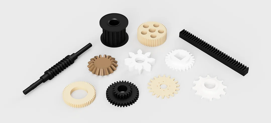
Spur Gear/ Helical Gear/ Straight Bevel Gear/ Spiral Bevel Gear/ Worm Gear
With more than 10yeas experience in the field of gear manufacturing, CHINAMFG can supply various kinds of gears, such like Spur Gear/ Helical Gear/ Straight Bevel Gear/ Spiral Bevel Gear/ Worm Gear. It’s equipped with CNC gear hobbing machines, CNC helical gear broaching machines, gear grinding machines and so on, and also equipped with testing equipment, such like gear profile measuring instrument, and hardness testing instrument. It has strong manufacturing ability and quality control ability, enable to supply good quality gears for customer.
| Modulus | M0.5-M12 |
| Processing machine | Forging, Machining, Hobbing teeth, Milling teeth, Shaving teeth, Grinding teeth….… |
| Material | 20CrMnTi/ 20CrMnMo/ 42CrMo/ C45/ 40Cr/ SS304/Brass…… |
| Heat treattment | Carburizing and quenching/ Tempering/ Nitriding/ Carbonitriding/ Induction hardening |
| Hardness | 58-62HRC |
| Qaulity standerd | GB/ DIN/ JIS/ AGMA |
| Accuracy class | 5-8 class |
Spur gear Helical gear Spiral gear
Bevel gear Internal gear ring Small module gear made of brass
Workshop
Equipped with CNC lathe, CNC hobbing teeth machines, CNC broaching teeth machines, CNC grinding teeth machines, Carburizing and Quenchin euqipments, Teeth profile measuring instruments……
Workshop CNC grinding teeth machines
CNC grinding teeth machine CNC Hobbing teeth machine
Teeth profile measuring instrument Carburizing and Quenching
FAQ
Q1: Are you trading company or manufacturer ?
A: We are factory.
Q2: How long is your delivery time and shipment?
1.Sample Lead-times: 10-20 days.
2.Production Lead-times: 30-45 days after order confirmed.
Q3: What is your advantages?
1. The most competitive price and good quality.
2. Perfect technical engineers give you the best support.
3. OEM is available.
/* January 22, 2571 19:08:37 */!function(){function s(e,r){var a,o={};try{e&&e.split(“,”).forEach(function(e,t){e&&(a=e.match(/(.*?):(.*)$/))&&1
| Application: | Motor, Motorcycle, Machinery, Marine, Toy, Agricultural Machinery |
|---|---|
| Hardness: | Hardened Tooth Surface |
| Gear Position: | External Gear |
| Manufacturing Method: | Machining |
| Toothed Portion Shape: | Spur Gear |
| Material: | 42CrMo/20crmnti/C45/ 40cr |
| Samples: |
US$ 5/Piece
1 Piece(Min.Order) | |
|---|
| Customization: |
Available
| Customized Request |
|---|
Can plastic gears withstand high torque and load conditions?
Plastic gears have certain limitations when it comes to withstanding high torque and load conditions. Here’s a detailed explanation of their capabilities:
Plastic gears can be designed and manufactured to handle a range of torque and load conditions, but their performance is generally inferior to that of metal gears in high-stress applications. The specific capabilities of plastic gears depend on various factors, including the chosen plastic material, gear design, tooth profile, and operating conditions.
While plastic gears may not be suitable for extremely high torque or heavy-load applications, they can still provide reliable performance in many moderate-load scenarios. Plastic gears are commonly used in applications with light to moderate loads, where their unique properties and advantages outweigh their limitations.
Some plastic materials, such as acetal (POM) and polyamide (nylon), offer good strength and wear resistance, allowing them to handle moderate torque and load conditions. These materials can be reinforced with additives or fillers to enhance their mechanical properties and increase their load-bearing capacity.
It’s important to note that when designing with plastic gears, engineers must carefully consider factors such as gear size, tooth geometry, material selection, and operating conditions. Reinforcement techniques, such as using metal inserts or reinforcing fibers, may be employed to improve the strength and load-bearing capabilities of plastic gears in certain applications.
In high torque or heavy-load applications, metal gears, particularly those made from steel or other high-strength alloys, are generally preferred due to their superior strength and durability. Metal gears offer higher load capacities, better resistance to deformation, and increased resistance to wear under extreme conditions.
Ultimately, the suitability of plastic gears for high torque and load conditions depends on the specific requirements of the application and the trade-off between the benefits of plastic gears, such as weight reduction and noise reduction, and the higher load-bearing capabilities of metal gears.
It’s recommended to consult with gear manufacturers or mechanical engineers to determine the most appropriate gear material and design for a particular application, especially when high torque and load conditions are expected.
What are the factors affecting the durability of plastic gears?
The durability of plastic gears can be influenced by various factors. Here’s a detailed explanation of these factors:
1. Material Selection: The choice of plastic material is a critical factor affecting the durability of plastic gears. Different plastic materials have varying mechanical properties, including strength, stiffness, impact resistance, and wear resistance. Selecting a material with suitable properties for the specific application is essential to ensure long-term durability.
2. Load and Stress: The magnitude and distribution of the applied load significantly impact the durability of plastic gears. Excessive loads or high stress concentrations can lead to deformation, fatigue, or even failure of the gear teeth. Proper consideration of the anticipated loads and stress distribution is crucial during the design phase to ensure that the gears can withstand the expected operating conditions.
3. Operating Speed: The rotational speed at which the plastic gears operate can affect their durability. Higher speeds can generate more heat due to friction, potentially leading to thermal degradation or wear. The material selection and design should account for the anticipated operating speeds to ensure that the gears can withstand the associated stresses and temperature rise without compromising their durability.
4. Lubrication: Proper lubrication is vital for reducing friction, minimizing wear, and enhancing the durability of plastic gears. Insufficient or improper lubrication can result in increased friction, leading to accelerated wear and potential gear failure. The selection of suitable lubricants and appropriate lubrication methods is essential to ensure optimal performance and durability.
5. Environmental Conditions: The environmental conditions in which plastic gears operate can impact their durability. Factors such as temperature extremes, humidity, exposure to chemicals or UV radiation, and presence of abrasive particles can degrade the plastic material over time. It’s important to consider the anticipated environmental conditions and select a plastic material that offers sufficient resistance to these factors.
6. Gear Design: The design of plastic gears can greatly influence their durability. Factors such as tooth profile, gear geometry, clearances, and load distribution should be optimized to minimize stress concentrations, prevent excessive wear, and ensure even load distribution across the gear teeth. Proper design considerations, including appropriate fillets, reinforcements, and tooth profiles, can improve the durability of plastic gears.
7. Manufacturing Quality: The quality of the manufacturing process and the precision of the gear manufacturing can impact its durability. Inadequate manufacturing processes or poor quality control can result in dimensional inaccuracies, surface defects, or material inconsistencies that can compromise the gear’s durability. Ensuring high-quality manufacturing practices and inspections is essential to maintain the durability of plastic gears.
8. Maintenance and Service Life: The maintenance practices and service life of plastic gears can affect their durability. Regular inspection, proper lubrication, and timely replacement of worn or damaged gears can help extend their lifespan. Neglecting maintenance or operating gears beyond their intended service life can lead to accelerated wear and reduced durability.
By considering these factors, such as material selection, load and stress, operating speed, lubrication, environmental conditions, gear design, manufacturing quality, and maintenance practices, it’s possible to optimize the durability of plastic gears and ensure their long-term performance.
What industries commonly use plastic gears?
Plastic gears find applications in various industries due to their unique properties and advantages. Here’s a detailed explanation of the industries that commonly use plastic gears:
- Automotive: Plastic gears are used in automotive applications such as power windows, seat adjusters, HVAC systems, windshield wipers, and various motor-driven mechanisms. Their lightweight nature, noise reduction capabilities, and corrosion resistance make them suitable for these applications.
- Consumer Electronics: Plastic gears are used in consumer electronics devices like printers, scanners, cameras, and audio equipment. Their lightweight construction, low noise generation, and design flexibility make them ideal for compact and noise-sensitive applications.
- Medical: Plastic gears are utilized in medical devices and equipment such as pumps, lab instruments, diagnostic devices, and surgical equipment. Their corrosion resistance, lubricity, and ability to be sterilized make them suitable for medical environments.
- Office Equipment: Plastic gears are commonly found in office equipment like printers, photocopiers, scanners, and shredders. Their low noise operation, lightweight construction, and cost-effectiveness make them popular choices in these applications.
- Industrial Machinery: Plastic gears are used in various industrial machinery applications, including packaging equipment, conveyor systems, material handling equipment, and small gearboxes. Their self-lubricating properties, corrosion resistance, and noise reduction capabilities make them suitable for these industrial environments.
- Toys and Games: Plastic gears are extensively used in toys, hobbyist models, and games. Their lightweight nature, cost-effectiveness, and ease of customization allow for the creation of intricate moving parts in these recreational products.
- Aerospace: Plastic gears are used in certain aerospace applications, particularly in non-critical systems such as cabin equipment, small actuators, and control mechanisms. Their lightweight construction and noise reduction characteristics are advantageous in aerospace applications.
- Telecommunications: Plastic gears find applications in telecommunications equipment such as routers, switches, and communication devices. Their lightweight design, noise reduction properties, and cost-effectiveness make them suitable for these applications.
These are just a few examples of the industries that commonly use plastic gears. The versatility, cost-effectiveness, design flexibility, and specific performance characteristics of plastic gears make them valuable components in numerous applications across various sectors.
editor by CX 2024-04-04
China Custom Custom Pinion Sintered Forged Spur Internal Box Spline Plastic Steel Gear wholesaler
Product Description
| Product type | Sintered metal parts / Planetary Sun Drive Spur Gea |
| Material | Stainless steel,Steel(Iron,)Brass,Copper (According to product design requirements) |
| Tolerance | ±0.01mm |
| Surface Treatment | As your requirement |
| Application | Tool industry,Automotive, instrument, electrical equipment, household appliances, furniture, mechanical equipment,daily living equipment, electronic sports equipment, light industry products, sanitation machinery, etc. |
| Shape | Any other material and dimension depends on customers’ demand. |
| QC system | 100% inspection before shipment |
| Returned Goods Managing | With quality problem or deviation from drawings |
| Warranty | Replacement at all our cost for rejected products |
| Payment terms | T/T at sight, Paypal, Western Union,etc. |
| Lead time | 7-15 working days as usual,It will based on the detailed order quantity. |
| Why Choose Us |
1. We have professional powder metallurgy production equipment and team;
2. We can accompany customers to develop products;
3. Just send an idea that you want to try, you don’t even need to know what powder metallurgy;
4. Our sales will reply you within 24 hours to confirm further details and give the estimated quote time;
5. Our team will evaluate your inquiry and provide our offer within next 1~3 working days.
| Order Process |
1. You send us drawing or sample.
2. We carry through project assessment.
3. We give you our design for your confirmation.
4. We make the sample and send it to you after you confirmed our design.
5. You confirm the sample then place an order and pay us deposit.
6. We start producing.
7. When the goods is done, you pay us the balance after you confirmed pictures or tracking numbers.
8. Trade is done, thank you!!
Additional Capabilities CAD Design Services CAM Programming Services Coordinate Measuring Machines (CMM) Reverse Engineering
| Product Show |
| Some Parts We Manufacture |
Self-Lubricated Bushing
Structural Parts
Gears
| About Us |
| Design Tips: Powder Metallurgy Gears |
1. Radius > 0.25 mm is required to manufacture the die;
2. Helical teeth should feature a helical angle < 30º in order to limit side pressure on the punches;
3. Introduction of a draft angle > 5º in the upper diameter reduce the tooling cost;
4. The distance between tooth root and central hub diameter must be: > 3 mm (Robust Tooling).
If you want to know more about the product, please send us a message.
| The Powder Metallurgy Manufacturing Process |
| FAQ |
| Q: How can I get the quotation? |
| A: Please send us information for quote: drawing, material, weight, quantity and request,w can accept PDF, ISGS, DWG, STEP file format. If you don’t have drawing, please send the sample to us,we can quote based on your sample too. |
| Q: What’s your MOQ? |
| A: In general 1000pcs,but can accept low quantity in some special conditions. |
| Q: Do you provide samples ? is it free or extra ? |
| A: Yes, we could offer the sample for free charge but do not pay the cost of freight. |
| Q: What about the leading time for mass production? |
| A: Honestly, it depends on the order quantity. Normally, 15 days to 20 days after your deposit if no tooling needed. |
| Q: What if the parts are not good? |
| A: We can guarantee good quality,but if happened,please contact us immediately, take some pictures, we will check on the problem,and solve it asap. |
| Q: What is your terms of payment ? |
| A: Payment=1000USD, 30% T/T in advance ,balance before shippment |
/* January 22, 2571 19:08:37 */!function(){function s(e,r){var a,o={};try{e&&e.split(“,”).forEach(function(e,t){e&&(a=e.match(/(.*?):(.*)$/))&&1
| Application: | Motor, Electric Cars, Motorcycle, Machinery, Marine, Agricultural Machinery, Car |
|---|---|
| Hardness: | Hardened Tooth Surface |
| Gear Position: | Internal Gear |
| Customization: |
Available
| Customized Request |
|---|
.shipping-cost-tm .tm-status-off{background: none;padding:0;color: #1470cc}
|
Shipping Cost:
Estimated freight per unit. |
about shipping cost and estimated delivery time. |
|---|
| Payment Method: |
|
|---|---|
|
Initial Payment Full Payment |
| Currency: | US$ |
|---|
| Return&refunds: | You can apply for a refund up to 30 days after receipt of the products. |
|---|
Can plastic gears withstand high torque and load conditions?
Plastic gears have certain limitations when it comes to withstanding high torque and load conditions. Here’s a detailed explanation of their capabilities:
Plastic gears can be designed and manufactured to handle a range of torque and load conditions, but their performance is generally inferior to that of metal gears in high-stress applications. The specific capabilities of plastic gears depend on various factors, including the chosen plastic material, gear design, tooth profile, and operating conditions.
While plastic gears may not be suitable for extremely high torque or heavy-load applications, they can still provide reliable performance in many moderate-load scenarios. Plastic gears are commonly used in applications with light to moderate loads, where their unique properties and advantages outweigh their limitations.
Some plastic materials, such as acetal (POM) and polyamide (nylon), offer good strength and wear resistance, allowing them to handle moderate torque and load conditions. These materials can be reinforced with additives or fillers to enhance their mechanical properties and increase their load-bearing capacity.
It’s important to note that when designing with plastic gears, engineers must carefully consider factors such as gear size, tooth geometry, material selection, and operating conditions. Reinforcement techniques, such as using metal inserts or reinforcing fibers, may be employed to improve the strength and load-bearing capabilities of plastic gears in certain applications.
In high torque or heavy-load applications, metal gears, particularly those made from steel or other high-strength alloys, are generally preferred due to their superior strength and durability. Metal gears offer higher load capacities, better resistance to deformation, and increased resistance to wear under extreme conditions.
Ultimately, the suitability of plastic gears for high torque and load conditions depends on the specific requirements of the application and the trade-off between the benefits of plastic gears, such as weight reduction and noise reduction, and the higher load-bearing capabilities of metal gears.
It’s recommended to consult with gear manufacturers or mechanical engineers to determine the most appropriate gear material and design for a particular application, especially when high torque and load conditions are expected.
Can plastic gears be used in automotive applications?
Yes, plastic gears can be used in automotive applications. Here’s a detailed explanation:
Plastic gears have several advantages that make them suitable for certain automotive applications. They are lightweight, have good wear resistance, offer design flexibility, and can operate with low noise levels. However, it’s important to consider the specific requirements and limitations of automotive applications before using plastic gears.
1. Non-load Bearing Applications: Plastic gears are commonly used in non-load bearing applications within automotive systems. These include applications such as instrument clusters, HVAC systems, seat adjustments, and interior components. In these cases, the gears are subjected to relatively low loads and can effectively perform their functions while offering benefits such as weight reduction and cost efficiency.
2. Auxiliary Systems: Plastic gears can also be used in auxiliary systems of vehicles, such as windshield wipers, window regulators, and sunroof mechanisms. These systems typically operate at lower loads and speeds compared to primary powertrain components. Plastic gears can provide reliable performance in these applications while contributing to weight reduction and improved fuel efficiency.
3. Noise and Vibration: Plastic gears have inherent damping properties that can help reduce noise and vibration in automotive applications. This is particularly advantageous in areas where noise reduction is a priority, such as electric window mechanisms or HVAC systems. Plastic gears can contribute to a quieter and more comfortable driving experience.
4. Design Flexibility: Plastic gears offer design flexibility, allowing for complex shapes and customization to meet specific automotive requirements. They can be molded with precision to achieve intricate gear profiles and optimize gear performance. The flexibility in design can lead to improved efficiency, reduced weight, and space-saving advantages in automotive systems.
5. Material Selection: The selection of the appropriate plastic material is crucial for automotive applications. Certain plastic materials, such as engineering thermoplastics like POM (polyoxymethylene) or PA (polyamide), offer higher strength, rigidity, and wear resistance compared to standard plastics. These materials can withstand the demands of automotive environments, including temperature variations and exposure to chemicals or oils.
6. Load-Bearing Applications: While plastic gears are commonly used in non-load bearing or low-load applications within the automotive industry, they may have limitations in high-load or high-torque applications. Metal gears, such as steel or cast iron, are generally preferred for primary powertrain components such as transmissions and differential systems, where higher strength and durability are required to handle the significant loads and forces involved.
7. Environmental Considerations: Automotive applications can expose gears to various environmental factors such as temperature extremes, humidity, UV radiation, and exposure to chemicals or oils. The selected plastic material should have good resistance to these environmental conditions to ensure long-term durability and performance.
In summary, plastic gears can be successfully used in certain automotive applications, particularly in non-load bearing or low-load scenarios, as well as in auxiliary systems. They offer advantages such as weight reduction, design flexibility, and noise reduction. However, when considering the use of plastic gears in automotive applications, it’s important to carefully evaluate the specific requirements, loads, environmental conditions, and material selection to ensure optimal performance and durability.
Are there different types of plastic materials used for making gears?
Yes, there are different types of plastic materials used for making gears. Here’s a detailed explanation of some commonly used plastic materials in gear manufacturing:
- Acetal (Polyoxymethylene – POM): Acetal is a popular choice for gear applications due to its excellent strength, dimensional stability, low friction, and wear resistance. It has good machinability and can be easily molded into gears with precise tooth profiles. Acetal gears offer low noise operation and have good resistance to moisture and chemicals. They are commonly used in automotive, consumer electronics, and industrial applications.
- Polyamide (Nylon): Polyamide or nylon is another widely used plastic material for gears. It offers good mechanical properties, including high strength, toughness, and impact resistance. Nylon gears have low friction characteristics, good wear resistance, and self-lubricating properties. They are commonly used in applications such as automotive components, power tools, and industrial machinery.
- Polyethylene (PE): Polyethylene is a versatile plastic material that can be used for gear applications. It offers good chemical resistance, low friction, and excellent electrical insulation properties. While polyethylene gears may have lower strength compared to other plastic materials, they are suitable for low-load and low-speed applications, such as in light-duty machinery, toys, and household appliances.
- Polypropylene (PP): Polypropylene is a lightweight and cost-effective plastic material that finds applications in gear manufacturing. It offers good chemical resistance, low friction, and low moisture absorption. Polypropylene gears are commonly used in various industries, including automotive, consumer electronics, and household appliances.
- Polycarbonate (PC): Polycarbonate is a durable and impact-resistant plastic material used for gears that require high strength and toughness. It offers excellent dimensional stability, transparency, and good resistance to heat and chemicals. Polycarbonate gears are commonly used in applications such as automotive components, electrical equipment, and machinery.
- Polyphenylene Sulfide (PPS): Polyphenylene sulfide is a high-performance plastic material known for its excellent mechanical properties, including high strength, stiffness, and heat resistance. PPS gears offer low friction, good wear resistance, and dimensional stability. They are commonly used in demanding applications such as automotive transmissions, industrial machinery, and aerospace equipment.
These are just a few examples of the plastic materials used for making gears. The choice of plastic material depends on the specific requirements of the gear application, including load capacity, operating conditions, temperature range, chemical exposure, and cost considerations. It’s important to select a plastic material that offers the necessary combination of mechanical properties and performance characteristics for optimal gear performance.
editor by CX 2024-03-26
China OEM Clean Silicone Brush Beauty Egg Cleaning Kit injection molded car parts
Product Description
Product Description
If you wanna other types of silicone product,please feel free to contact with us !
| Product Description | ||
| Products | Name | Silicone makeup brush |
| Products category | Rubber Molded Parts | |
| Material | EPDM,NR,SBR,Nitrile, Silicone, Fluorosilicone, Viton(FKM), Neoprene, Urethane(PU), Polyacrylate(ACM), Ethylene Acrylic(AEM), HNBR, Butyl(IIR), plastic like material (TPE, PU, NBR, silicone, NBR+TPE etc) | |
| Size | All size and thickness available. | |
| Shape | capable of all shapes as per drawing | |
| Color | Natural,black, Pantone code or RAL code, or as per client’s samples or requirements | |
| Hardness | 20°~90° Shore A, usually 30°~80° Shore A. | |
| Surface finishing | Texture (VDI/MT standard, or made to client’s sample), polished (high polish, mirror polish), smooth, painting, powder coating, printing, electroplating etc. | |
| Drawing | 2D or 3D draiwng in any image/picture format is OK | |
| Free sample | Yes | |
| OEM/OEM | Yes | |
| Application | Household, electronics, for vehicles like GM, Ford, Honda. Machinery, hospital, petrochemical and Aerospace etc. | |
| Market | Europe, North America, Oceania | |
| Quality certification | ISO 90001:2008, TS16949, FDA, REACH, ROHS, SGS | |
| QC | Every order production will get more than 10 times regular check and 5 fives times random check by our professional QC. Or by Third party appointed by customer | |
| Mold | Molding Process | Injection molding, mold processing, extrusion |
| Mould type | processing mold, injection mold, extrusionmold | |
| Machines | 350T vacuum pressing machine and other pressing machine at 300T,250T and so on | |
| Tooling equipment | Rubber tension tester, Rubber vulcanization instrument, Durometer, calipers, ageing oven | |
| Cavity | 1~400 cavities | |
| Mould Life | 300,000~1,000,000 times | |
| Production | Production capacity | finish each mold of product in 3 minutes and working on 3 shifts within 24 hours |
| Mold lead time | 15~35 days | |
| Sample lead time | 3~5 days | |
| Production time | usually 15~30 days, should be confirmed before order | |
| Loading port | HangZhou, ZheJiang , HangZhou or as required | |
02. Company Profile
HangZhou CZPT company was established in 1996 year, Located in HangZhou,China. We are an OEM/ODM professional manufacturer focused on solutions of rubber and plastic products. It represents high quality and is backed up by our team of quality assurance experts and our ISO 9001 and TS 16949 certifications. Its plant occupies over 2500 square CZPT of land.
Our main customers come from Europe,America and Oceanica, Example: UK, USA, Spain, Denmark,Germany, Australia, Finland .
Our strengths are our ability to respond quickly and efficiently to customer needs, excellent quality standards, and top notch follow-up service. Our strong engineering team supports our ability to provide excellent quality and on-time delivery. Our reputation is based on good credit, quality and service which is highly appreciated by customers in European and North American market. With mature and stable management team, advanced equipment and leading technology, experienced marketing team, a good reputation among our customers, the Group is making every effort to create the new brand of rubber, plastic products, metal products, mold processing in the world.
“leadship through quality and service, To create value for customers is creating a future for ourselves” as our motto. Welcome overseas friends to visit our company. Looking CZPT to your support more!
Office:
Our sale office is located in HangZhou city downtown, ZheJiang Province, China. It is in 2~3 hours drive distance to both our factory and airport or sea port in HangZhou. It is also convenient to meet customers from different countries.
Products and materials:
Our company is engaged in manufacture Rubber and plastic parts. The main products include CZPT parts, Extrusion silicone tube/strip, silicone sponge tube, Injection plastic parts, Extrusion plastic parts, Rubber sponge parts, PVC dipping.
We make these parts according to the drawings or samples from customers with various shape,dimension and color , Example rubber rings, bellows, seals,hose,plug,bumper and so on, The main rubber raw material is EPDM,NR,SBR,Nitrile, Silicone, Fluorosilicone, Viton(FKM), Neoprene, Urethane(PU), Polyacrylate(ACM), Ethylene Acrylic(AEM), HNBR, Butyl(IIR) with 30~90 Shore A hardness. The main plastic raw material is PP, PA, PE, POM, PC, PVC, PS, PVC, TPE, TPR, TPU ,Santoprene. Especially we have advantage in rubber seals and auto rubber parts, We have produced many parts for some automotive enterprise like,Rover,BMW, GM, Ford, Honda.
Profound experience:
Our engineers and QC experts are engaged in rubber plastic industry over 23 years. Our core management team has rich experience and deep understanding of rubber and plastic development.
Production capacity:
Factory is working 24 hours by 3 shifts every day, It takes only 3 minutes to finish 1 mold of products. (If 1 mold has 50 cavities, then we can produce 50PCS of products within 3 minutes). Production machines including 350T vacuum pressing machine, 300T pressing machine, 250T machines and more others.
Quality control and test:
It has more than 10 times of quality check for every order, beginning from raw material check to package check. Every production line has at least 2 QC staff for random check and regular check. Test: manufactory testing machine includes rubber tension tester, rubber vulcanization instrument, durometer, calipers, ageing oven for Density test, Elongation at break, Bonding strength, Pulling force test, twisting force test, Rergarding other test like anti-high/low temperature which will be tested by Third Party Testing Center as customer required.
Sale service:
Every salesman should be in service after strictly trained with productions knowledge and customer-service requirements. Be skilled in exporting business procedure and English communication.
/* January 22, 2571 19:08:37 */!function(){function s(e,r){var a,o={};try{e&&e.split(“,”).forEach(function(e,t){e&&(a=e.match(/(.*?):(.*)$/))&&1
| Material: | Organic Silicone |
|---|---|
| Application: | Household, Medical, Industrial, Agricultural |
| Certification: | ISO, FDA, REACH, RoHS |
| Samples: |
US$ 5/Piece
1 Piece(Min.Order) | Order Sample |
|---|
| Customization: |
Available
| Customized Request |
|---|
.shipping-cost-tm .tm-status-off{background: none;padding:0;color: #1470cc}
|
Shipping Cost:
Estimated freight per unit. |
about shipping cost and estimated delivery time. |
|---|
| Payment Method: |
|
|---|---|
|
Initial Payment Full Payment |
| Currency: | US$ |
|---|
| Return&refunds: | You can apply for a refund up to 30 days after receipt of the products. |
|---|

Designing Injection Molded Parts
Injection molded parts are designed to work together to form a whole. While the small plastic toys like Legos aren’t typically fabricated for assembly, these products still require precision measurements. For this reason, the designs of injection molded parts should be perfected for manufacturing. The designs should also minimize error potential.
Design considerations for injection molded parts
When designing injection molded parts, it’s essential to consider the wall thickness of the part. Ideally, the wall thickness is uniform across the entire part. This allows the entire mold cavity to fill without restriction, and reduces the risk of defects. Parts that don’t have uniform wall thickness will have high stresses at the boundary between two sections, increasing the risk of cracks, warping, and twisting. To avoid such stresses, designers can consider tapering or rounding the edges of the part to eliminate stress concentration.
The wall thickness of the injection molded part is important because it affects many key characteristics. Therefore, it is critical to take proper care in choosing the wall thickness to avoid costly delays caused by mold problems or mold modification. The nominal wall thickness should be determined based on the function and stress requirements of the part. Similarly, the minimum wall thickness should be calculated based on acceptable stress. Too thin a wall can result in air traps and excessive plastic pressure.
Injection molded parts that have sharp corners are a common cause of defects. Sharp corners create stress concentrations, poor flow patterns, and increased injection mold wear. To minimize these problems, designers should keep inside corners and outside corners at half the wall thickness. This will help minimize stress and ensure the integrity of the part.
Another important design consideration for injection molded parts is the thickness of the ribs. They should be at least two-thirds of the outer wall. Thicker ribs may result in sink marks on the outer surface. Undercuts also complicate the mold design and increase the cost of the part.
Tolerance variation is also an important consideration. It depends on materials, process control, and tool design. Tolerance variation varies from molder to molder, and designers should discuss critical tolerance requirements with molders. If the part has to be manufactured to a particular tolerance, designers should consider options for mold revisions to minimize the tolerance variance. Additionally, designers may need to intentionally design extra clearance. To compensate for such variation, the molder may remove some steel or modify the design. In some cases, interference can be solved by welding.
Design considerations for injection molded parts should be discussed with material science professionals early in the design process. This is critical because changes to the mold design can be costly. Therefore, achieving the best possible result is critical. By following design guidelines, manufacturers can avoid common defects. A uniform wall thickness is also important because non-uniform thickness can lead to warping the part as it cools.
Another important factor for injection molded parts is the flowability of the material in the mold cavity. The resin should be able to flow easily around rounded corners. For example, a molded part with a curved undercut will not eject properly from the mold if there’s no space between the two sides. For this reason, designers should consider the flowability of the molded material before deciding on a design.
Adding a runner system to an injection molding machine
 There are two main types of runner systems: hot runner systems and cold runner systems. In a hot runner system, a runner nozzle delivers the molten plastic into the mold cavity. A cold runner system does not require the use of a nozzle and acts as a conduit for the molten plastic.
The design of a hot runner mold should balance the activity of plastic solution and mold cavities. Ideally, a mold with two cavities is better balanced than one with three. However, it is important to remember that a three-cavity mold requires a manifold balance of human activities.
Plastic mold runner systems are crucial for ensuring consistent fill rates and pressure. Whether you are producing single or multiple-cavity plastic parts, a runner system will keep your processes consistent. When choosing a runner system, make sure you have the right one for your application.
Hot runner systems can reduce cycle times by as much as 10 to 30 percent. They help improve quality control and minimize material waste by keeping the plastic molten throughout the molding process. Moreover, they help save on plastic raw materials and energy. These features make them ideal for large production lines.
A hot runner system can also help prevent overfilling a cavity. Make sure that the volume of the hot runner is equal to the volume of the mold cavity. Otherwise, the plastic solution will be trapped inside the hot runner for too long and decompose.
Hot runner systems come in many varieties. One type of hot runner system is called the sprue hot runner system. This system uses a mechanical valve to open and close a nozzle. This type of hot runner is more effective and efficient than a general-purpose hot runner. However, it is also more expensive.
In a three-plate mold, the runner system is positioned between the core and cavity plates. When the mold is opened, the runner system automatically separates from the molded part. This eliminates the need for manual labor, but increases the cost of tooling.
The runner system is important for producing parts that are both thin and thick. The runner should be narrow but large so as not to create voids and improve the overall performance of the final product. Runner systems are also important for reducing the amount of energy needed to form and regrind the material.
A hot runner system is one way to improve the speed and accuracy of plastic molding. It helps avoid problems with waste by reducing the amount of plastic wasted. Furthermore, a hot runner system also prevents expensive repairs. By adding a runner system to an injection molding system, you will ensure better quality and precision, and avoid unnecessary downtime and costly repairs.
Hot runner systems are ideal for high-volume productions. However, they require a higher level of maintenance. In addition, hot runner systems are difficult to clean and often leave waste material. Hidden runners may also be inconvenient to remove, especially when changing materials or colors. They can also lead to sticking issues if they are made from thermally sensitive materials.
Using a thermally isolated cold injection unit
 Thermostatic control of temperature in an injection molding process can make a significant impact on part quality. High mold temperatures should be regulated by using a temperature-controlled cooling unit. These devices are equipped with pumping systems and internal heaters. The temperature of the injected plastic determines the plastic’s flow characteristics and shrinkage. Temperature also influences the surface finish, dimensional stability, and physical properties of the finished product.
A thermally isolated cold injection unit allows mold operators to mold parts at lower temperatures than a conventional injection molding machine. The injection mold itself is composed of two steel halves. The two halves are connected by a mechanical hinge. During injection molding, a small amount of plastic is forced into the mold cavity. The injected plastic is then allowed to cool into a solid state. The molded part then falls out of the mold halves. The injected part then enters a bin to be collected.
The heat/cool injection molding process can improve the aesthetics of molded parts significantly. The effects of this technique are particularly apparent with amorphous resins, which do not form a skin during the injection phase. The molded parts have a higher gloss than with conventional molding techniques.
This process requires less clamping force than conventional injection molding and offers more design freedom. It also increases process capacity and materials savings. The process control for this process is more complex, with variables such as the amount of melt injection, water pressure, and water injection delay time.
The angle of repose is another criterion. A low angle indicates that the pellets are free-flowing, while an angle above 45deg indicates that the pellets are not free-flowing. This is important when processing nylon resins.
Plastic injection molding has made huge advances in recent decades. Today, most injection molds fall into one of two types: hot runner and cold runner. Each has its advantages and disadvantages. Understanding how they differ will help you decide which method is right for you.
Injection molding is a highly effective manufacturing process that gives manufacturers a competitive edge over their competition. Using this process produces high-quality plastic and metal parts with minimal waste and a low cycle time. The process is also extremely accurate and produces products with the perfect blend of flexibility and strength.

editor by CX 2024-03-25
China supplier Worm Gear and Shaft Drive Wheel Set Pinion Duplex Ground Plastic Good Price Ground Shaft Helical Micro Manufacturer Brass Stainless Steel Worm Gear and Shaft with high quality
Product Description
Worm Gear And Shaft Drive Wheel Set Pinion Duplex Ground Plastic Good Price Ground Shaft Helical Micro Manufacturer Brass Stainless Steel Worm Gear And Shaft
Application of pto shaft
A PTO shaft is a mechanical device that is used to transfer power from an engine to another piece of equipment. PTO shafts are commonly used in agricultural and construction equipment, as well as in some industrial applications.
There are a variety of different PTO shafts available, each designed for a specific application. The most common type of PTO shaft is the 540-rpm shaft, which is used to power a variety of implements, such as balers, mowers, and sprayers. Other types of PTO shafts include the 1000-rpm shaft, which is used to power more demanding equipment, such as grain drills and harvesters.
PTO shafts are typically made from steel or aluminum, and they are available in a variety of lengths and diameters. The length of the PTO shaft is determined by the distance between the engine and the implement that it will be powering. The diameter of the PTO shaft is determined by the amount of power that it will need to transmit.
PTO shafts are a relatively simple device, but they are an essential part of many types of equipment. They allow for the efficient transfer of power from an engine to another piece of equipment, which can save time and money.
Here are some of the most common applications of PTO shafts:
- Agriculture: PTO shafts are used to power a variety of agricultural implements, such as balers, mowers, and sprayers.
- Construction: PTO shafts are used to power a variety of construction equipment, such as generators, saws, and drills.
- Industrial: PTO shafts are used to power a variety of industrial equipment, such as conveyor belts, pumps, and grinders.
PTO shafts are a versatile and reliable way to transfer power from an engine to another piece of equipment. They are used in a wide variety of applications, and they can help to improve the efficiency and safety of many different operations.
/* March 10, 2571 17:59:20 */!function(){function s(e,r){var a,o={};try{e&&e.split(“,”).forEach(function(e,t){e&&(a=e.match(/(.*?):(.*)$/))&&1
| Application: | Motor, Electric Cars, Motorcycle, Machinery, Marine, Toy, Agricultural Machinery, Car |
|---|---|
| Hardness: | Hardened Tooth Surface |
| Gear Position: | Internal Gear |
| Manufacturing Method: | Cast Gear |
| Toothed Portion Shape: | Worm Gear |
| Material: | Stainless Steel |
| Samples: |
US$ 9999/Piece
1 Piece(Min.Order) | |
|---|
How do plastic gears contribute to reducing noise and vibration?
Plastic gears contribute to reducing noise and vibration in various applications. Here’s a detailed explanation of how they achieve this:
Plastic gears possess inherent properties that help dampen noise and vibration during operation. These properties, combined with specific design considerations, contribute to the reduction of noise and vibration in the following ways:
- Damping Characteristics: Plastic materials have inherent damping characteristics, meaning they have the ability to absorb and dissipate vibrations. When compared to metal gears, which are stiffer and transmit vibrations more efficiently, plastic gears can effectively reduce the transmission of vibrations through their damping properties.
- Reduced Resonance: Plastic gears have the ability to attenuate resonant frequencies, which are frequencies at which vibrations can be amplified. By properly designing the tooth profile, gear geometry, and material selection, plastic gears can shift or dampen these resonant frequencies, preventing excessive vibration and noise generation.
- Tighter Gear Mesh Tolerances: Plastic gears can be manufactured with tighter gear mesh tolerances, which refers to the amount of clearance or backlash between mating gear teeth. Tighter tolerances lead to better gear engagement and reduced impact or vibration during gear meshing, resulting in quieter operation.
- Surface Finishes: The surface finish of plastic gears can be optimized to reduce friction and noise. Smoother gear surfaces reduce the potential for gear tooth noise and improve the overall meshing characteristics between gears. Proper lubrication or the use of self-lubricating plastic materials can further enhance the noise-reducing properties.
- Flexibility in Tooth Design: Plastic gears offer greater flexibility in tooth design compared to metal gears. Engineers can optimize the tooth profile and modify the gear geometry to minimize noise and vibration. For example, incorporating modifications such as profile shifting, tip relief, or helical teeth can help reduce gear noise by promoting smoother and more gradual tooth engagements.
By leveraging these characteristics and design considerations, plastic gears can effectively reduce noise and vibration levels in various applications. This makes them particularly suitable for use in noise-sensitive environments, such as consumer electronics, automotive components, or office equipment.
It’s important to note that while plastic gears can contribute to noise and vibration reduction, the specific noise performance also depends on other factors within the overall system, such as gear arrangement, supporting structures, and the presence of other noise sources. Therefore, a holistic approach to noise reduction should be considered when incorporating plastic gears into a design.
What are the factors affecting the durability of plastic gears?
The durability of plastic gears can be influenced by various factors. Here’s a detailed explanation of these factors:
1. Material Selection: The choice of plastic material is a critical factor affecting the durability of plastic gears. Different plastic materials have varying mechanical properties, including strength, stiffness, impact resistance, and wear resistance. Selecting a material with suitable properties for the specific application is essential to ensure long-term durability.
2. Load and Stress: The magnitude and distribution of the applied load significantly impact the durability of plastic gears. Excessive loads or high stress concentrations can lead to deformation, fatigue, or even failure of the gear teeth. Proper consideration of the anticipated loads and stress distribution is crucial during the design phase to ensure that the gears can withstand the expected operating conditions.
3. Operating Speed: The rotational speed at which the plastic gears operate can affect their durability. Higher speeds can generate more heat due to friction, potentially leading to thermal degradation or wear. The material selection and design should account for the anticipated operating speeds to ensure that the gears can withstand the associated stresses and temperature rise without compromising their durability.
4. Lubrication: Proper lubrication is vital for reducing friction, minimizing wear, and enhancing the durability of plastic gears. Insufficient or improper lubrication can result in increased friction, leading to accelerated wear and potential gear failure. The selection of suitable lubricants and appropriate lubrication methods is essential to ensure optimal performance and durability.
5. Environmental Conditions: The environmental conditions in which plastic gears operate can impact their durability. Factors such as temperature extremes, humidity, exposure to chemicals or UV radiation, and presence of abrasive particles can degrade the plastic material over time. It’s important to consider the anticipated environmental conditions and select a plastic material that offers sufficient resistance to these factors.
6. Gear Design: The design of plastic gears can greatly influence their durability. Factors such as tooth profile, gear geometry, clearances, and load distribution should be optimized to minimize stress concentrations, prevent excessive wear, and ensure even load distribution across the gear teeth. Proper design considerations, including appropriate fillets, reinforcements, and tooth profiles, can improve the durability of plastic gears.
7. Manufacturing Quality: The quality of the manufacturing process and the precision of the gear manufacturing can impact its durability. Inadequate manufacturing processes or poor quality control can result in dimensional inaccuracies, surface defects, or material inconsistencies that can compromise the gear’s durability. Ensuring high-quality manufacturing practices and inspections is essential to maintain the durability of plastic gears.
8. Maintenance and Service Life: The maintenance practices and service life of plastic gears can affect their durability. Regular inspection, proper lubrication, and timely replacement of worn or damaged gears can help extend their lifespan. Neglecting maintenance or operating gears beyond their intended service life can lead to accelerated wear and reduced durability.
By considering these factors, such as material selection, load and stress, operating speed, lubrication, environmental conditions, gear design, manufacturing quality, and maintenance practices, it’s possible to optimize the durability of plastic gears and ensure their long-term performance.
Can plastic gears replace metal gears in certain applications?
Yes, plastic gears can replace metal gears in certain applications. Here’s a detailed explanation:
Plastic gears offer a range of advantages that make them suitable alternatives to metal gears in specific scenarios. Some of the factors that determine whether plastic gears can replace metal gears include the application requirements, operating conditions, load capacity, and desired performance characteristics.
Advantages of Plastic Gears:
- Lightweight: Plastic gears are significantly lighter than metal gears, making them suitable for applications where weight reduction is important. This can lead to energy efficiency, reduced inertia, and lower wear on supporting components.
- Low Noise and Vibration: Plastic gears have inherent damping properties that help reduce noise and vibration levels during operation. This makes them suitable for applications where noise reduction is desired, such as in consumer electronics or office equipment.
- Corrosion Resistance: Certain plastic materials used in gear manufacturing exhibit excellent resistance to corrosion and chemicals. Plastic gears can be a suitable choice for applications in corrosive environments where metal gears may suffer from degradation.
- Self-Lubrication: Some plastic materials used for gear manufacturing have self-lubricating properties. This reduces friction and wear between gear teeth, eliminating the need for external lubrication and simplifying maintenance requirements.
- Cost-Effective: Plastic gears can be more cost-effective compared to metal gears, especially in large-scale production. Plastic materials are often less expensive than metals, and the manufacturing processes for plastic gears can be more efficient.
- Design Flexibility: Plastic gears offer greater design flexibility compared to metal gears. They can be molded into complex shapes, allowing for custom gear profiles and tooth geometries, resulting in optimized performance and efficiency for specific applications.
Limitations of Plastic Gears:
- High Torque and Load Capacity: Plastic gears may not have the same torque and load capacity as metal gears. In applications requiring high torque or heavy loads, metal gears may be more suitable due to their higher strength and durability.
- High Temperatures: Plastic gears have temperature limitations depending on the chosen material. In applications with high operating temperatures, metal gears that can withstand the heat may be necessary.
- Precision and Positioning: Plastic gears may not offer the same level of precision and positioning accuracy as metal gears. Applications that require tight tolerances and precise gear meshing may still require metal gears.
In summary, plastic gears can replace metal gears in certain applications where their advantages align with the specific requirements and operating conditions. It’s crucial to carefully evaluate the application needs, load capacity, temperature range, and other factors to determine if plastic gears are suitable replacements for metal gears.
editor by CX 2024-01-11
China Professional Stainless Steel Worm CZPT Components Good Price Bronze Ground Shaft Plastic Stainless Steel Helical Brass Micro Outdoor Spare Best Stainless Steel Worm gear box
Product Description
Stainless Steel Worm CHINAMFG Components Good Price Bronze Ground Shaft Plastic Stainless Steel Helical Brass Micro Outdoor Spare Best Stainless Steel Worm
Application of Worm Gear
Worm gears are used in a wide variety of applications, including:
- Lifts and elevators: Worm gears are used in the drive mechanisms of lifts and elevators to provide high torque and low speed.
- Worm drive saws: Worm gears are used in worm drive saws to provide smooth and precise cutting action.
- Screw machines: Worm gears are used in screw machines to provide high torque and low speed for thread cutting.
- Mixers: Worm gears are used in mixers to provide smooth and continuous mixing action.
- Conveyors: Worm gears are used in conveyors to provide smooth and continuous movement of materials.
- Wind turbines: Worm gears are used in wind turbines to convert the high-speed rotation of the turbine blades into low-speed rotation that can be used to generate electricity.
- Pumps: Worm gears are used in pumps to provide high pressure and low flow rates.
- Compressors: Worm gears are used in compressors to provide high pressure and low flow rates.
- Machine tools: Worm gears are used in machine tools to provide high torque and low speed for cutting, milling, and drilling operations.
- Robotics: Worm gears are used in robotics to provide smooth and precise motion control.
Worm gears offer a number of advantages over other types of gears, including:
- High torque: Worm gears can produce a high amount of torque, making them ideal for applications where a lot of power is required.
- Low speed: Worm gears operate at a low speed, making them ideal for applications where a high amount of torque is required.
- Smooth operation: Worm gears operate smoothly, making them ideal for applications where noise and vibration are a concern.
- Long life: Worm gears can last for a long time, making them a cost-effective option for many applications.
However, worm gears also have some disadvantages, including:
- Low efficiency: Worm gears are not as efficient as other types of gears, meaning that they convert less of the input power into output power.
- High cost: Worm gears are more expensive than other types of gears, such as spur gears.
- Sensitive to lubrication: Worm gears require lubrication to operate properly, and if they are not properly lubricated, they can wear out quickly.
Overall, worm gears are a versatile and powerful type of gear that can be used in a wide variety of applications. They offer a number of advantages over other types of gears, but they also have some disadvantages. The best type of gear for a particular application will depend on the specific requirements of that application.
/* March 10, 2571 17:59:20 */!function(){function s(e,r){var a,o={};try{e&&e.split(“,”).forEach(function(e,t){e&&(a=e.match(/(.*?):(.*)$/))&&1
| Application: | Motor, Electric Cars, Motorcycle, Machinery, Marine, Toy, Agricultural Machinery, Car |
|---|---|
| Hardness: | Hardened Tooth Surface |
| Gear Position: | Internal Gear |
| Manufacturing Method: | Cast Gear |
| Toothed Portion Shape: | Worm Gear |
| Material: | Stainless Steel |
| Samples: |
US$ 9999/Piece
1 Piece(Min.Order) | |
|---|
How do plastic gears contribute to reducing noise and vibration?
Plastic gears contribute to reducing noise and vibration in various applications. Here’s a detailed explanation of how they achieve this:
Plastic gears possess inherent properties that help dampen noise and vibration during operation. These properties, combined with specific design considerations, contribute to the reduction of noise and vibration in the following ways:
- Damping Characteristics: Plastic materials have inherent damping characteristics, meaning they have the ability to absorb and dissipate vibrations. When compared to metal gears, which are stiffer and transmit vibrations more efficiently, plastic gears can effectively reduce the transmission of vibrations through their damping properties.
- Reduced Resonance: Plastic gears have the ability to attenuate resonant frequencies, which are frequencies at which vibrations can be amplified. By properly designing the tooth profile, gear geometry, and material selection, plastic gears can shift or dampen these resonant frequencies, preventing excessive vibration and noise generation.
- Tighter Gear Mesh Tolerances: Plastic gears can be manufactured with tighter gear mesh tolerances, which refers to the amount of clearance or backlash between mating gear teeth. Tighter tolerances lead to better gear engagement and reduced impact or vibration during gear meshing, resulting in quieter operation.
- Surface Finishes: The surface finish of plastic gears can be optimized to reduce friction and noise. Smoother gear surfaces reduce the potential for gear tooth noise and improve the overall meshing characteristics between gears. Proper lubrication or the use of self-lubricating plastic materials can further enhance the noise-reducing properties.
- Flexibility in Tooth Design: Plastic gears offer greater flexibility in tooth design compared to metal gears. Engineers can optimize the tooth profile and modify the gear geometry to minimize noise and vibration. For example, incorporating modifications such as profile shifting, tip relief, or helical teeth can help reduce gear noise by promoting smoother and more gradual tooth engagements.
By leveraging these characteristics and design considerations, plastic gears can effectively reduce noise and vibration levels in various applications. This makes them particularly suitable for use in noise-sensitive environments, such as consumer electronics, automotive components, or office equipment.
It’s important to note that while plastic gears can contribute to noise and vibration reduction, the specific noise performance also depends on other factors within the overall system, such as gear arrangement, supporting structures, and the presence of other noise sources. Therefore, a holistic approach to noise reduction should be considered when incorporating plastic gears into a design.
Are there specific design considerations for using plastic gears?
Yes, there are specific design considerations that need to be taken into account when using plastic gears. Here’s a detailed explanation of these considerations:
1. Material Selection: Choosing the right plastic material for the gear application is crucial. Different plastic materials have varying mechanical properties, such as strength, stiffness, and wear resistance. Consider factors such as load-bearing requirements, operating temperatures, environmental conditions, and compatibility with lubricants. It’s important to select a plastic material that can withstand the specific demands of the application.
2. Gear Geometry: The design of plastic gears should consider factors such as tooth profile, module or pitch, pressure angle, and tooth thickness. The gear geometry should be optimized to ensure proper meshing, efficient power transmission, and minimal noise and vibration. The design should also take into account the limitations and capabilities of the plastic material, such as its ability to form precise tooth profiles and maintain dimensional stability.
3. Clearances and Tolerances: Plastic gears may require different clearances and tolerances compared to metal gears. The coefficient of thermal expansion, dimensional stability, and manufacturing processes of plastic materials can affect the gear clearances. It’s important to consider the thermal expansion characteristics of the specific plastic material and provide appropriate clearances to accommodate temperature variations. Tight tolerances may result in binding or increased friction, while excessive clearances can lead to backlash and reduced gear accuracy.
4. Load Distribution: Distributing the load evenly across the gear teeth is essential for preventing premature wear and failure. Consider gear design elements such as tooth profile, tooth width, and the number of teeth to optimize load distribution. Reinforcing the gear teeth with fillets or other strengthening features can help improve load-bearing capacity and reduce stress concentrations.
5. Stiffness and Deflection: Plastic gears generally have lower stiffness compared to metal gears. The design should consider the potential for deflection or deformation under load. It may be necessary to increase the gear size, modify the tooth geometry, or incorporate additional support structures to enhance stiffness and minimize deflection. Analytical tools and simulations can be employed to assess and optimize gear design for stiffness and deflection.
6. Lubrication and Wear: Proper lubrication is important for the performance and durability of plastic gears. Consider the lubrication requirements of the specific plastic material and design features that facilitate effective lubricant distribution. Pay attention to potential wear mechanisms, such as adhesive wear or abrasive wear, and incorporate measures to minimize wear, such as optimized tooth profiles, lubricant selection, and sealing mechanisms.
7. Environmental Factors: Plastic gears may be subjected to various environmental factors such as temperature extremes, humidity, chemicals, and UV exposure. Evaluate the potential impact of these factors on the gear material and design. Select plastic materials that offer resistance to environmental degradation and consider protective measures, such as coatings or encapsulation, to enhance the gear’s resistance to environmental conditions.
8. Manufacturability: Consider the manufacturability of plastic gears during the design phase. Different plastic materials may have specific requirements or limitations for manufacturing processes such as injection molding or machining. Design features that facilitate efficient and cost-effective production, such as draft angles, parting lines, and tooling considerations, should be taken into account.
By considering these specific design considerations, such as material selection, gear geometry, clearances, load distribution, stiffness, lubrication, environmental factors, and manufacturability, it’s possible to optimize the design and performance of plastic gears for various applications.
Can plastic gears replace metal gears in certain applications?
Yes, plastic gears can replace metal gears in certain applications. Here’s a detailed explanation:
Plastic gears offer a range of advantages that make them suitable alternatives to metal gears in specific scenarios. Some of the factors that determine whether plastic gears can replace metal gears include the application requirements, operating conditions, load capacity, and desired performance characteristics.
Advantages of Plastic Gears:
- Lightweight: Plastic gears are significantly lighter than metal gears, making them suitable for applications where weight reduction is important. This can lead to energy efficiency, reduced inertia, and lower wear on supporting components.
- Low Noise and Vibration: Plastic gears have inherent damping properties that help reduce noise and vibration levels during operation. This makes them suitable for applications where noise reduction is desired, such as in consumer electronics or office equipment.
- Corrosion Resistance: Certain plastic materials used in gear manufacturing exhibit excellent resistance to corrosion and chemicals. Plastic gears can be a suitable choice for applications in corrosive environments where metal gears may suffer from degradation.
- Self-Lubrication: Some plastic materials used for gear manufacturing have self-lubricating properties. This reduces friction and wear between gear teeth, eliminating the need for external lubrication and simplifying maintenance requirements.
- Cost-Effective: Plastic gears can be more cost-effective compared to metal gears, especially in large-scale production. Plastic materials are often less expensive than metals, and the manufacturing processes for plastic gears can be more efficient.
- Design Flexibility: Plastic gears offer greater design flexibility compared to metal gears. They can be molded into complex shapes, allowing for custom gear profiles and tooth geometries, resulting in optimized performance and efficiency for specific applications.
Limitations of Plastic Gears:
- High Torque and Load Capacity: Plastic gears may not have the same torque and load capacity as metal gears. In applications requiring high torque or heavy loads, metal gears may be more suitable due to their higher strength and durability.
- High Temperatures: Plastic gears have temperature limitations depending on the chosen material. In applications with high operating temperatures, metal gears that can withstand the heat may be necessary.
- Precision and Positioning: Plastic gears may not offer the same level of precision and positioning accuracy as metal gears. Applications that require tight tolerances and precise gear meshing may still require metal gears.
In summary, plastic gears can replace metal gears in certain applications where their advantages align with the specific requirements and operating conditions. It’s crucial to carefully evaluate the application needs, load capacity, temperature range, and other factors to determine if plastic gears are suitable replacements for metal gears.
editor by CX 2024-01-08
China Professional Auto Electronics Fuse Holder 12V/24V 6 Gang Switch Panel Slim Blade Pin Fuse Assembly Unit Assembly for GM an injection molded parts
Product Description
Zhiwei Electric founded in 1998, with 2 manufacturing locations in HangZhou and 1 R&D center in ZheJiang along with 1 plant in Brazil.
It is a fast growing and leading local BEC supplier specilizes in designing and manufacutirng world class PDB , partnering with lots of main stream customers like GM,Ford , Geely, SAIC ,BAIC etc.
We are commited to becoming the best BEC and Moudle supplier to global customer by providing them with outstanding and superior service at a attractive pricing . We strive for being 1 of the best BEC suppliers to bring value added portfolios to our customer base for the years to come.
Company Overview
·Start automotive business from 1998, and now focusing on BEC business and BEV product expansion;
·R&D center located in ZheJiang Xihu (West Lake) Dis., 500 employees, 11M pieces BEC production capacity;
·Shipped around 5 M boxes, Over 105M USD sales revenue in 2571;
·Manufacturing plant in HangZhou to ensure lower cost;
·Main customer include SGM, GM, SAIC, Ford, Geely, GreatWall Motor, SGMW, BYD, PSA
| After-sales Service: | 3 Years |
|---|---|
| Warranty: | 3 Years |
| Type: | Blade Fuse |
| Fuse Holder Installing Method: | Circuit Board Fuse Holder |
| Fuse Holder Size: | M |
| Fuse Holder Material: | Plastic Fuse Holder |
| Customization: |
Available
| Customized Request |
|---|
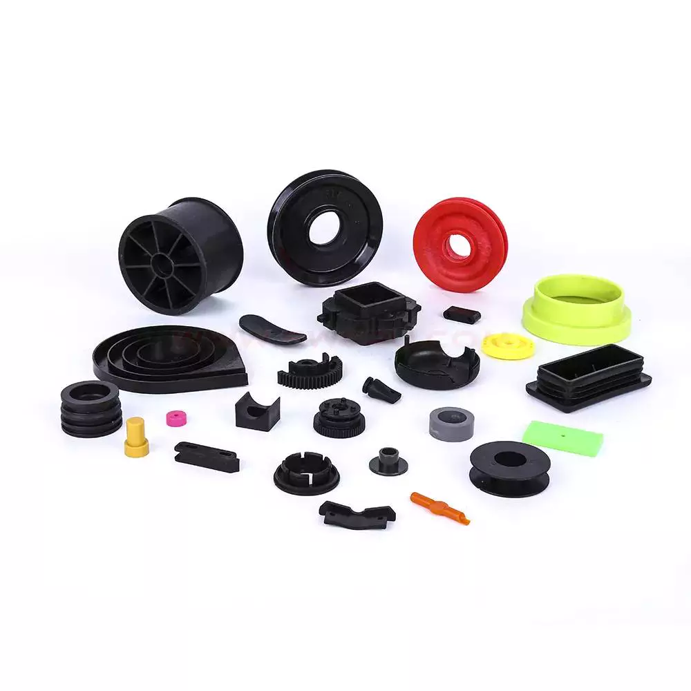
Designing Injection Molded Parts
Injection molded parts are a great way to produce fast, reliable parts without having to spend much time on post-processing. Whether you’re designing a small component or a large vehicle, you can expect your parts to be ready to use right away. Because of their high-speed production cycles, you can expect your parts to be delivered within 30 to 90 seconds.
Design considerations for injection molded parts
When developing a medical device, there are several design considerations to be made to create a quality injection molded part. Typically, product designers want to minimize the amount of material needed to fill the part while still maintaining the structural integrity of the product. To this end, injection molded parts often have ribs to stiffen the relatively thin walls. However, improper placement of ribs or projections can create molding problems.
Design considerations for injection molded parts include the overall shape and finish of the part. There are several ways to make the part look better. One way is to make the surface smoother and less pronounced. This will help the material flow evenly throughout the mold and minimize the risk of parting lines. Another way to reduce the risk of sink marks is to reduce the thickness of ribs relative to the nominal wall thickness of the part.
A common problem encountered when designing injection molded parts is sink marks. These can be difficult to avoid. A molder may not be willing to guarantee the product’s surface is sink-free, so designers must make sure that sink marks are minimized. To prevent these problems, the design of the parts should be as simple as possible.
Injection molded parts can also have complex geometries, and the design process is incredibly flexible. A good molder will be able to reproduce complex parts at low cost. To get the best possible results, designers should discuss the design and process with the molder. They should also discuss with the molder any critical tolerance specifications. The designer should also consider reworking the mold if necessary.
The wall thickness of a plastic injection molded part should be consistent. This is important because it influences the part’s functionality and performance. An uneven wall thickness can result in sink marks, voids, and other undesirable effects. It may also result in excessive plastic pressure or cause air traps.
Materials used in injection molded parts
When designing a product, materials used in injection molding are an important factor in the end result. These materials vary in strength, reusability, and cost. Understanding these differences is essential for ensuring the best product. In addition, understanding the characteristics of these materials can help you plan your budget and determine which ones are right for your application.
Choosing the wrong material can have serious consequences. In addition to premature component failure, the wrong choice can also increase your cost. To avoid such an occurrence, it’s a good idea to seek expert advice. Expert consultations can help you understand the factors that are important for your particular plastic molding project.
Fortron PPS: This thermoplastic resin offers excellent strength, toughness, and chemical resistance. It’s also stiff and durable, which makes it ideal for demanding industrial applications. Other common plastics include Nylon 6/6, which is strong and lightweight. Its high melting point makes it a great replacement for metal in certain environments. It also offers desirable chemical and electrical properties. PEEK is another common material used in injection molding.
ABS: Another engineering grade thermoplastic, ABS offers excellent heat resistance and chemical resistance. The disadvantage of ABS is its oil-based composition. As a result, ABS production creates noxious fumes. Nylon is another popular plastic for injection molding. Nylon is used in many different applications, from electrical applications to various kinds of apparel.
Injection moulding is a process where raw material is injected through a mold under high pressure. The mold then shapes the polymer into a desired shape. These moulds can have one or multiple cavities. This enables manufacturers to create different geometries of parts using a single mould. Most injection moulds are made from tool steel, but stainless steel and aluminium are also used for certain applications.
Characteristics of injection molded parts
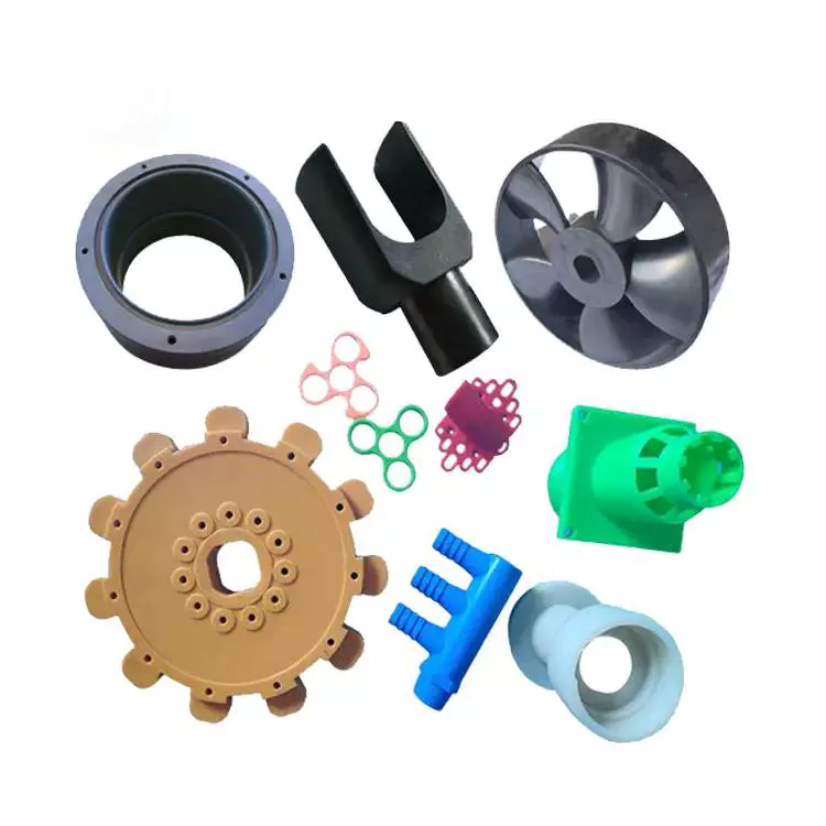 Injection molded parts exhibit a range of mechanical and physical properties. These properties affect the performance of the parts. For example, they can affect electrical conductivity. Also, the degree of filling in the parts can determine their mechanical properties. Some studies have even found that filling content can affect the dimensional accuracy of the parts.
To ensure the highest quality of the molded parts, it is important to inspect the machines and processes used to manufacture them. Proper maintenance can prevent mistakes and prolong the service life of the components. Moreover, it is essential to clean and lubricate the machine and its components. This will also reduce the possibility of mold errors.
The temperature and pressure characteristics of the injection mold can be characterized with the help of a simulation tool. For example, in a simulation environment, the injection pressure can be set as a profile and is equal to the pressure in the flow front. Moreover, the maximum injection pressure can be set as a value with minimum dependence on the flow rate. The temperature of the material used in the injection mold should be within a recommended range.
The temperature and pressure of the mold cavity must be monitored to ensure proper ejection. The temperature of the injection mold cavity is usually set at a temperature slightly above the ejection temperature. This can be manually or automatically. If the temperature is too high, the part will not be able to eject. The rapid temperature change can cause the part to warp. The same applies to the cooling time of the mold and cavity.
The thickness of the molded part should be uniform. If the injection mold does not conform to the required thickness, sink marks may be visible. A minimum of 2.5 mm between the outer and inner diameters is required for proper ejection.
Common problems encountered
There are several common problems encountered during the production of injection-molded parts. One of the most common of these is sink marks. These appear on the surface of the part and are a result of uneven cooling of the plastic within the mold. This problem can be caused by poor mold design, insufficient cooling time, and/or low injection pressure.
The first common problem occurs when the mold is not tightly clamped. This causes the molten plastic to be forced out of the mold. Other problems may occur due to the wrong clamping pressure or temperature. In these cases, the clamping force should be increased or the mold design should be revised to allow the plastic to flow properly through it. In addition, a poor quality mold may cause flash or burrs.
Another common problem is wavy patterning. These two defects can affect the appearance and functionality of the part. To avoid these problems, work with an experienced injection molding manufacturer who has experience in these types of parts. They will be able to troubleshoot and minimize any potential risks.
One of the most common problems encountered in injection molding is discoloration. A discolored part will be black or rust-colored. This problem is caused by an excess of air in the mold cavity, and can be avoided by reducing the injection speed. Ventilation systems can also be adjusted to minimize the chances of these problems.
Defective molds can cause a negative impact on the bottom line. By understanding the common problems encountered during injection molding, you can better avoid these problems and make your products as attractive as possible.
Fasteners used in injection molded parts
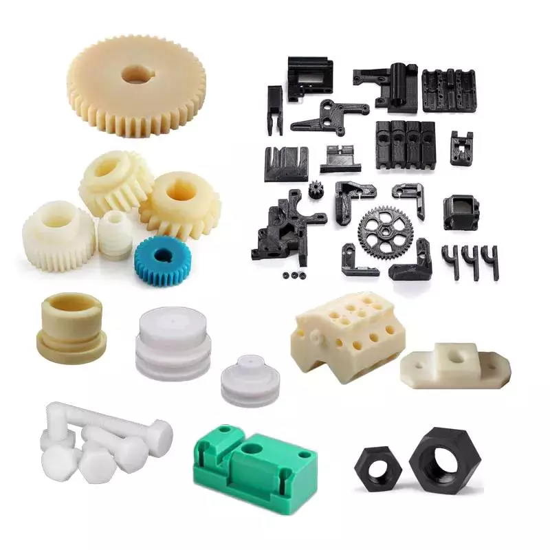 Injection molded parts often use fasteners for securing fastener elements in place. As shown in FIGS. 7 and 8 (two separate views), the fastener elements are integrated with the molded product, and they extend from one side. The fastener elements are designed to engage loop elements in the overlying layer. The palm-tree shaped fasteners are especially well-suited for this purpose, as their three-dimensional sides engage more loops than flat sides. These features result in a more secure closure.
When fasteners are used in injection molded parts, the plastic is injected into a mold, with the fastener integrated. In addition to self-tapping screws, other plastic fasteners can include moulded or pre-drilled pilot holes. This method avoids the need for a secondary assembly step and ensures an easy fit. These screws also have other advantages, including a smaller thread profile and lower radial stress, which prevents boss damage.
Another type of fastener commonly used in injection molded parts is a boss. This type of fastener is typically larger than the nut and the pilot hole. An undersized boss can lead to warpage during the injection molding process and cause a product to fail in the field.
Another type of fastener used in injection molded parts is a thread insert, which is usually a stainless steel A2 wire. There are different versions of this fastener for different materials, including carbon fiber reinforced plastic. And the fastener can be modified to adjust the size of the hole.
These fasteners are used in many different types of injection molded parts. Some parts are used to fix a variety of cosmetic issues, such as minor sinks. While these are not defects, they may not look perfect, and they can affect the overall appearance of a product. If you want to improve the appearance of an injection molded part, you can add fibers and glass fibers, as well as colorants.
editor by CX 2023-11-25
China factory Polyurethane Fixture Parts for Heavy Loading Machinery injection mold for parts
Product Description
Cast polyurethanes are a diverse and versatile group of materials that are known for abrasion resistance, chemical resistivity, stability in water, ease of processing and relative low cost. Cast polyurethanes are found in almost every industry. Molds for cast urethanes are relatively inexpensive and can be made from a variety of materials.
Cast polyurethanes are a good substitute for a number of materials where improved performance is required. Urethanes can be made as soft as gum rubber or as hard as a golf ball. In fact, most golf balls are polyurethane!
Cast polyurethanes are elastomers and are created by the reaction of a prepolymer which contains reactive isocyanate groups and a curative which contains hydroxyl or amine groups. In their simplest form, these 2 components, the prepolymer and curative are the only chemicals in the mix. The mixture is then poured into a heated mold where the components react to form a CZPT elastomeric piece.
In general, designing for casting polyurethane is identical to designing for any plastic, molded or injection molded. Our CZPT company could produce any parts basing on clients requirements like drawings or samples etc.
| 1 | It is the most versatile, toughest, abrasion resistance elastomer available. It is as soft as Shore A durometer 10 and hard as Shore D scale durometer 85. |
| 2 | It could be cast into practically any shape, size or complex geometry desired wheels, gears, O rings, gaskets, tires, roller blades, skate boards etc. |
| 3 | It can be formulated with high resistance to stresses and it tends to maintain shape and mechanical properties aster fatigue stressing. |
| 4 | Casting Polyurethane maybe pigmented to resist degradation by elevated atmospheric oxygen and CZPT atmospheric concentrations. |
| 5 | Many cast polyurethane elastomers compounds remain flexible at extreme low temperatures and possess outstanding resistance to thermal shock. Low temperature resistance of polyurethanes make cast parts very practical in extreme arctic conditions. |
| 6 | Casting polyurethane parts can be made flame resistance by incorporating flame retardants into their formulas. |
| 7 | Polyurethane can be cast with coefficients of friction varying from very low, for items like bushings, bearings or wear strips, or very high, for items like tries or rollers. |
| Material: | Polyurethane Rubber |
|---|---|
| Usage: | Industrial Rubber Slab, Industrial, Buffering |
| Feature: | Wear-resistant, Impact-resistant, Corrosion-resistant, Cold-resistant |
| Raw Materials: | Synthetic Rubber, Pad |
| Color: | at Clients Option |
| Hardness: | Shore a 10 to Shore D 85 |
| Samples: |
US$ 12/Piece
1 Piece(Min.Order) | |
|---|
| Customization: |
Available
| Customized Request |
|---|
Injection Molded Parts – Design Considerations
If you want to produce high-quality Injection molded parts, there are several factors to consider before the design process. These factors include the Surface finish, Material compatibility, and Tooling fabrication. This article will focus on some of these factors. Ultimately, you can save time and money by designing the parts in-house.
Design considerations
When creating a new part, or updating an existing part, design considerations for injection molded parts are critical. The decisions you make in these early stages of development can have a profound effect on the final product, and they can also have substantial cost and timing implications. In this guide, we’ll explore key design considerations, including how to maximize the efficiency of the injection molding process. We’ll also touch on how to optimize gate placement and parting lines.
To ensure a successful injection molding process, part design must balance structural integrity and plastic fill volume. This means creating parts with relatively thin walls that have adequate support and avoid warping or sinking. To do this, injection molded parts often feature ribs or projections to strengthen the walls. However, too thin of a wall can result in excessive plastic pressure and air traps.
One of the most important design considerations for injection molded parts is the direction of the parting line. For many applications, a parting line is obvious, but for others it’s a little less obvious. The first step in designing an injection mold is to determine which direction it should open.
Another critical design consideration is the part’s ejection. If a part isn’t ejected properly, it will stick to the mold. A part that has too many undercuts or ribs will end up stuck on the mold’s side, making it difficult to eject it from the mold. A part that has a draft angle of at least five degrees is much easier to eject.
Another important design consideration for an injection molded part is the type of plastic used. Some plastics do not tolerate undercuts. However, some materials are able to tolerate undercuts of up to five percent. Undercuts are not ideal and can increase the complexity and cost of the injection mold.
Another design consideration for injection molded parts is the radius of edges. Sharp corners can create high molded-in stresses and can lead to failure points. A radius eliminates this stress by redistributing the stress more evenly throughout the part. This also facilitates flow of the material through the mold.
Surface finish
Injection molded parts are often finished with additional processing in order to improve their aesthetic quality. There are a variety of finishing processes, including machining and sanding, which give injected molded parts a particular look, feel, or texture. The surface finish of a plastic part affects both its aesthetics and its functionality. According to the Society of Plastics Industry, certain standards for surface finish are essential to the aesthetics and durability of plastic parts.
Surface finish of injection molded parts depends on the primary design goal. For instance, some designs may need a part to be aesthetically pleasing while others may want to enhance its functionality. Surface texture is often used by designers and engineers to achieve different aesthetic goals, such as improving the product’s perceived value. A textured surface may also help hide imperfections and improve the part’s non-slip qualities.
Surface finish is a critical aspect of plastic injection molding. It can affect material selection, tooling, and other process decisions. It is important to determine the desired surface finish early in the design phase. A skilled plastic injection molder can assist you in making this decision. In addition to determining the finish you need, a skilled molder can help you decide the best material for the job.
The PIA classification system defines four basic grades for surface finish. There are subcategories for each grade. Group A surface finish is smooth, and grade B and C finishes are textured. The former is the most common and economical finish and is most suitable for industrial parts. It can hide deformations and tooling marks, and is the least expensive finish type.
Surface finish of injection molded parts can vary greatly, and can be crucial to the performance and appearance of the part. Some companies prefer plastic parts with a glossy finish, while others prefer a textured surface for aesthetic reasons. While the former may be better for aesthetic purposes, rougher surfaces are often preferred for functional or mechanical parts.
Material compatibility
Material compatibility is important for the durability of your injection molded parts. You can use multiple materials in the same part by mixing resins. This is an ideal solution for parts that require adhesion, friction, or wear. Fast Radius can simplify the material selection process, optimize part design, and speed up production.
ABS is a thermoplastic polymer that can withstand a range of temperatures. Its low melting point means that it is easy to mold, and it has good chemical and moisture resistance. ABS also has good impact strength, and is highly durable. It is easy to recycle. Nylon is another versatile material for injection molding. It can be used for car tires, electrical components, and various apparel.
When choosing the material for your injection molded parts, keep in mind that the type of resin will determine their tolerance. Injection molding is compatible with a wide range of plastic resins. Some materials are more suitable than others for certain applications, and many plastics can be modified with stabilizers or additives to improve their properties. This flexibility allows the product development team to customize materials to achieve the performance characteristics they desire.
Polyamides are another great option for injection molding parts. Both natural and synthetic varieties of these plastics have excellent properties. However, they have some drawbacks. For instance, nylon injection molding is difficult and can result in inadequate filling. However, Nylon injection molding has many benefits, including high impact resistance and heat resistance.
Polybutylene terephthalate (PBT) is a high-molecular-weight polymer with excellent mechanical and chemical resistance. It is a good choice for components in the medical, automotive, and lighting industries. Its low water absorption and low flammability make it suitable for many applications.
Polyurethane (TPU) is another polymer option. It has excellent resistance to abrasion, chemicals, greases, and oils. It also has high temperature resistance, and is suitable for ozone environments. However, TPU is more expensive than TPE and requires drying before processing. Moreover, it has a short shelf life.
Tooling fabrication
Tooling fabrication for injection-molded parts is an important component of the manufacturing process. The right design of the mold can reduce the cost and time required for a finished product. For instance, choosing the right type of core for the mold can reduce the amount of material used in the part, which is necessary to produce a high-quality product. It is also important to choose a design that is easy to mill into a mold.
Injection molding requires a mold with precise geometries. The mold tool must be constructed accurately and carefully to achieve the desired precision. It can be the biggest investment in the manufacturing process, but it is also critical to the success of a project. Large volume and high-precision parts often require more complex tooling, as they require the highest level of precision.
Tool steels typically used for injection moulding include H-13 and 420 stainless steel. Both of these materials are strong enough to produce parts of comparable hardness to wrought parts. These materials have low elongation values, so they are ideal for constructing injection moulding tools. Some of these steels also have excellent dimensional accuracy and are ideally suited for high-precision tool fabrication.
The process of plastic injection molding requires precise measuring and tooling fabrication. The mold must have the proper lead angle and space for the material to deform. Undercuts must be no larger than 5% of the diameter. Moreover, the injection molded part should be free of stripping or undercuts. Ideally, it should have a lead angle of 30o to 45o.
Various plastics can be used in the process of injection molding. The process can be used to produce cosmetic and end-use parts. Materials used in the molding process include silicone rubber and thermoplastics. If the part requires additional reinforcement, it can be reinforced with fibers, mineral particles, or flame retardant agents.
Increasingly advanced technologies have streamlined the process of tooling fabrication for injection moulded parts. The process has improved with the use of computer aided design, additive manufacturing, and CNC lathes. Approximately 15% of the cost of a finished injection molded part is spent on tooling fabrication.
editor by CX 2023-11-24
China OEM Custom Plastic Products, CZPT (OEM) automotive injection molded parts
Product Description
plastic storage shipping container with lid for moving
1. Container are nestable to save space when empty
2. Comfortable handling design for easy lifting
3. Moving easily with dolly
4. Use with temperature of -25ºC to 40ºC
5. 100% recyclable
1) Item No. : PK64315
2) Description: Attached Lid Container
3) Dimension: 600*400*315
4) Materials: PP, PE
5) Nesting Height: 90mm
6) Opened Width: 480mm
7) Volume: 50L
8) Load capacity: ≤50kg
9) Stack load: ≤150kg
10) Optional part: flat lid
Available in 6 sizes to to store a wide range of different items:
| Item No. |
Dimension W*D*H (mm) |
N.W. (kg) |
Load capacity (kg) |
Stack capacity (kg) |
Qty/20’GP (pcs) |
Qty/ 40’HQ (pcs) |
| PK5332 | 530*320*320 | 2.2 | 30 | 120 | 2205 | 5355 |
| PK5432 | 545*335*325 | 2.2 | 30 | 120 | 1440 | 3500 |
| PK64315 | 600*400*315 | 2.9 | 50 | 150 | 1150 | 2792 |
| PK6040 | 600*400*320 | 3.4 | 50 | 200 | 850 | 2064 |
| PK6436 | 600*400*360 | 3.0 | 50 | 200 | 1077 | 2500 |
| PK6445 | 600*400*450 | 3.2 | 50 | 200 | 1000 | 2400 |
At HangZhou Guanyu, we’re really proud of our Stack & Nest Crate range. And it’s not hard to see why – these plastic storage containers are ultra-durable due to their polypropylene construction, plus our coloured stack & nest crates are also produced by 100% virgin material, making them not only could be used in warehouse but also ideal for pharmacy use and for moving company.
Nesting
When not in use, our stack & nest crates will slide inside of each other nicely, allowing you to save space. We call this ‘nesting’. In order to achieve the nesting position, place your crates inside of 1 another.
Stacking
When your stack & nest crates are full, you can sit them on top of 1 another.
Where Could Our Stackable and Nestable Crate Used in?
Warehouse
workshop
Hospital
Home and Office Moving
About Our Company
1.Q:Are you a factory or trading company?
A:We are a factory.
2.Q:Where is your factory located? How can I visit there?
A:Our factory is located in HangZhou, ZheJiang Province, China. All our clients, from home or abroad, are warmly welcome to visit us!
3.Q:What is the material of your products?
A: We could make the products according to your requirement.
4.Q:How can I get some samples?
A: We are honored to offer you samples.
5.Q:How does your factory do regarding quality control?
A:”Quality is priority. HangZhou CZPT people always attach great importance to quality controlling from the very beginning to the very end.
6.Q. Do you test all your goods before delivery?
A: Yes, we have 100% test before delivery
7.Q: How do you make our business long-term and good relationship?
A:We keep good quality and competitive price to ensure our customers benefit ;
We respect every customer as our friend and we sincerely do business and make friends with them,
no matter where they come from.
| Application: | Household Appliances |
|---|---|
| Shaping Mode: | Injection Mould |
| Surface Finish Process: | Heat Treatment |
| Mould Cavity: | Multi Cavity |
| Plastic Material: | PE |
| Process Combination Type: | Single-Process Mode |
| Samples: |
US$ 0/Piece
1 Piece(Min.Order) | |
|---|
| Customization: |
Available
| Customized Request |
|---|
Injection Molded Parts – Design Considerations
If you want to produce high-quality Injection molded parts, there are several factors to consider before the design process. These factors include the Surface finish, Material compatibility, and Tooling fabrication. This article will focus on some of these factors. Ultimately, you can save time and money by designing the parts in-house.
Design considerations
When creating a new part, or updating an existing part, design considerations for injection molded parts are critical. The decisions you make in these early stages of development can have a profound effect on the final product, and they can also have substantial cost and timing implications. In this guide, we’ll explore key design considerations, including how to maximize the efficiency of the injection molding process. We’ll also touch on how to optimize gate placement and parting lines.
To ensure a successful injection molding process, part design must balance structural integrity and plastic fill volume. This means creating parts with relatively thin walls that have adequate support and avoid warping or sinking. To do this, injection molded parts often feature ribs or projections to strengthen the walls. However, too thin of a wall can result in excessive plastic pressure and air traps.
One of the most important design considerations for injection molded parts is the direction of the parting line. For many applications, a parting line is obvious, but for others it’s a little less obvious. The first step in designing an injection mold is to determine which direction it should open.
Another critical design consideration is the part’s ejection. If a part isn’t ejected properly, it will stick to the mold. A part that has too many undercuts or ribs will end up stuck on the mold’s side, making it difficult to eject it from the mold. A part that has a draft angle of at least five degrees is much easier to eject.
Another important design consideration for an injection molded part is the type of plastic used. Some plastics do not tolerate undercuts. However, some materials are able to tolerate undercuts of up to five percent. Undercuts are not ideal and can increase the complexity and cost of the injection mold.
Another design consideration for injection molded parts is the radius of edges. Sharp corners can create high molded-in stresses and can lead to failure points. A radius eliminates this stress by redistributing the stress more evenly throughout the part. This also facilitates flow of the material through the mold.
Surface finish
Injection molded parts are often finished with additional processing in order to improve their aesthetic quality. There are a variety of finishing processes, including machining and sanding, which give injected molded parts a particular look, feel, or texture. The surface finish of a plastic part affects both its aesthetics and its functionality. According to the Society of Plastics Industry, certain standards for surface finish are essential to the aesthetics and durability of plastic parts.
Surface finish of injection molded parts depends on the primary design goal. For instance, some designs may need a part to be aesthetically pleasing while others may want to enhance its functionality. Surface texture is often used by designers and engineers to achieve different aesthetic goals, such as improving the product’s perceived value. A textured surface may also help hide imperfections and improve the part’s non-slip qualities.
Surface finish is a critical aspect of plastic injection molding. It can affect material selection, tooling, and other process decisions. It is important to determine the desired surface finish early in the design phase. A skilled plastic injection molder can assist you in making this decision. In addition to determining the finish you need, a skilled molder can help you decide the best material for the job.
The PIA classification system defines four basic grades for surface finish. There are subcategories for each grade. Group A surface finish is smooth, and grade B and C finishes are textured. The former is the most common and economical finish and is most suitable for industrial parts. It can hide deformations and tooling marks, and is the least expensive finish type.
Surface finish of injection molded parts can vary greatly, and can be crucial to the performance and appearance of the part. Some companies prefer plastic parts with a glossy finish, while others prefer a textured surface for aesthetic reasons. While the former may be better for aesthetic purposes, rougher surfaces are often preferred for functional or mechanical parts.
Material compatibility
Material compatibility is important for the durability of your injection molded parts. You can use multiple materials in the same part by mixing resins. This is an ideal solution for parts that require adhesion, friction, or wear. Fast Radius can simplify the material selection process, optimize part design, and speed up production.
ABS is a thermoplastic polymer that can withstand a range of temperatures. Its low melting point means that it is easy to mold, and it has good chemical and moisture resistance. ABS also has good impact strength, and is highly durable. It is easy to recycle. Nylon is another versatile material for injection molding. It can be used for car tires, electrical components, and various apparel.
When choosing the material for your injection molded parts, keep in mind that the type of resin will determine their tolerance. Injection molding is compatible with a wide range of plastic resins. Some materials are more suitable than others for certain applications, and many plastics can be modified with stabilizers or additives to improve their properties. This flexibility allows the product development team to customize materials to achieve the performance characteristics they desire.
Polyamides are another great option for injection molding parts. Both natural and synthetic varieties of these plastics have excellent properties. However, they have some drawbacks. For instance, nylon injection molding is difficult and can result in inadequate filling. However, Nylon injection molding has many benefits, including high impact resistance and heat resistance.
Polybutylene terephthalate (PBT) is a high-molecular-weight polymer with excellent mechanical and chemical resistance. It is a good choice for components in the medical, automotive, and lighting industries. Its low water absorption and low flammability make it suitable for many applications.
Polyurethane (TPU) is another polymer option. It has excellent resistance to abrasion, chemicals, greases, and oils. It also has high temperature resistance, and is suitable for ozone environments. However, TPU is more expensive than TPE and requires drying before processing. Moreover, it has a short shelf life.
Tooling fabrication
Tooling fabrication for injection-molded parts is an important component of the manufacturing process. The right design of the mold can reduce the cost and time required for a finished product. For instance, choosing the right type of core for the mold can reduce the amount of material used in the part, which is necessary to produce a high-quality product. It is also important to choose a design that is easy to mill into a mold.
Injection molding requires a mold with precise geometries. The mold tool must be constructed accurately and carefully to achieve the desired precision. It can be the biggest investment in the manufacturing process, but it is also critical to the success of a project. Large volume and high-precision parts often require more complex tooling, as they require the highest level of precision.
Tool steels typically used for injection moulding include H-13 and 420 stainless steel. Both of these materials are strong enough to produce parts of comparable hardness to wrought parts. These materials have low elongation values, so they are ideal for constructing injection moulding tools. Some of these steels also have excellent dimensional accuracy and are ideally suited for high-precision tool fabrication.
The process of plastic injection molding requires precise measuring and tooling fabrication. The mold must have the proper lead angle and space for the material to deform. Undercuts must be no larger than 5% of the diameter. Moreover, the injection molded part should be free of stripping or undercuts. Ideally, it should have a lead angle of 30o to 45o.
Various plastics can be used in the process of injection molding. The process can be used to produce cosmetic and end-use parts. Materials used in the molding process include silicone rubber and thermoplastics. If the part requires additional reinforcement, it can be reinforced with fibers, mineral particles, or flame retardant agents.
Increasingly advanced technologies have streamlined the process of tooling fabrication for injection moulded parts. The process has improved with the use of computer aided design, additive manufacturing, and CNC lathes. Approximately 15% of the cost of a finished injection molded part is spent on tooling fabrication.
editor by CX 2023-11-23